

 English
 Português
 لالعربية
 Русский
 Bahasa Indonesia
 Français
 Türkçe
 Bahasa Melayu

Cable de fibra OPGW-4 con Tubo de acero inoxidable cubierto de aluminio | 12-144 núcleos | G.652D / G.655C para red eléctrica
High quality IEC607948 IEEE1138 standards for designing, testing, and producing with grade A materials available to ensure long-term reliability.
Engineering support supervising and providing its own line of accessories hardware.
Seal stainless steel tube superior protection to the fiber optical to moisture and extreme environmental conditions such as lightning.
To construct OPGW must cut power, resulting in greater loss, thus OPGW must be used in constructing a high-pressure line over 110kv.
Apply to the transformation of old lines.
What is OPGW Aluminum-Covered Stainless Steel Tube Fiber Cable
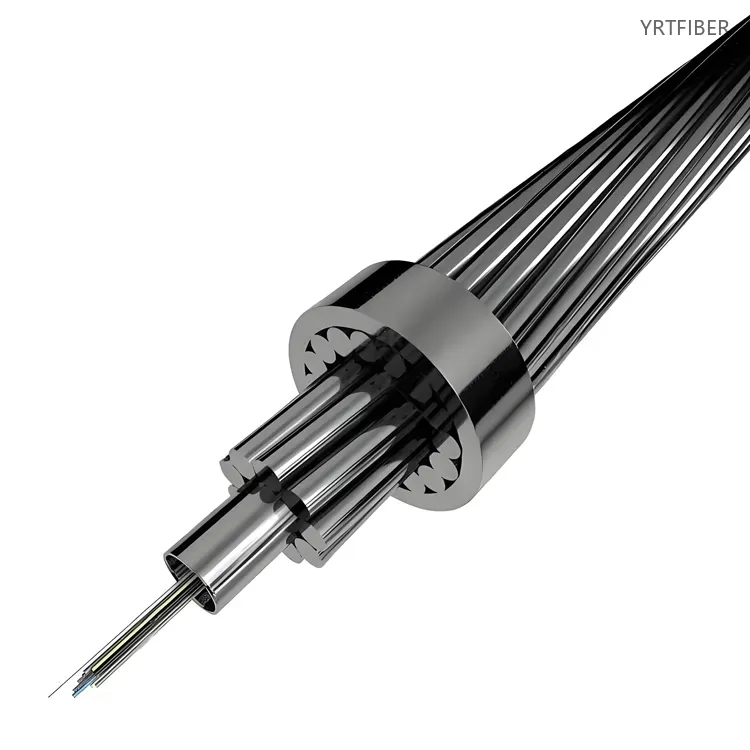
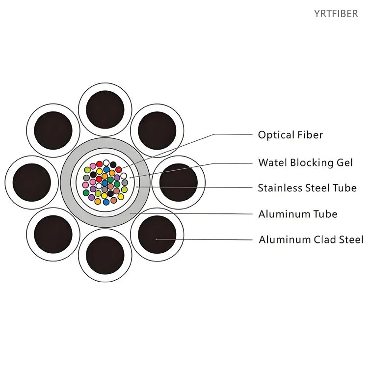
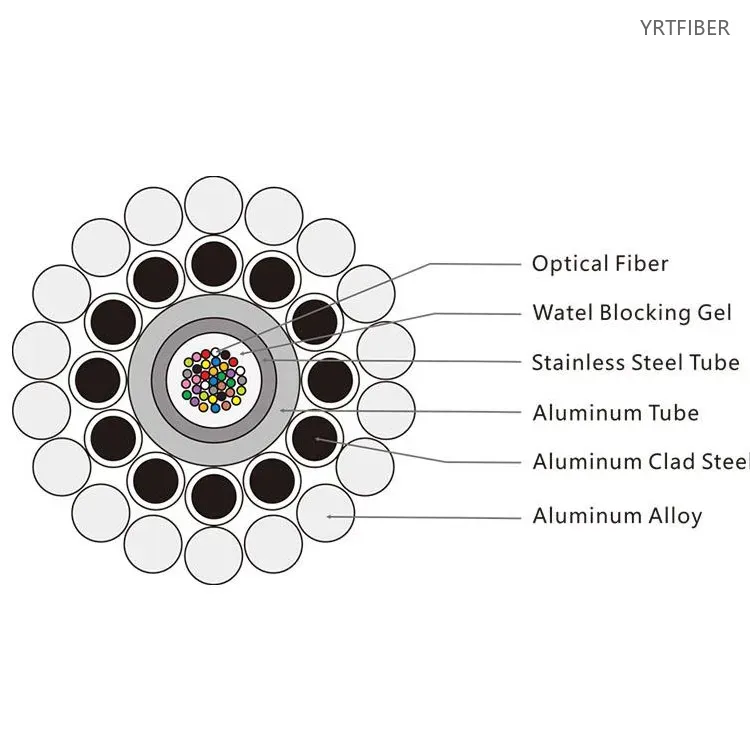
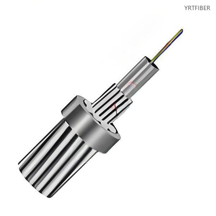
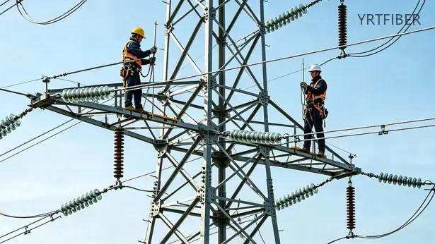
OPGW (Optical Fiber Composite Overhead Ground Wire) is a special type of optical cable that combines the functions of ground wire protection and fiber optic communication. It is usually deployed at the top of transmission line towers, serving both to replace traditional ground wires in withstanding lightning strikes and short-circuit currents, and to enable high-speed data transmission through the built-in optical fibers. Specifically, the "aluminum-clad stainless steel tube structure" refers to sealing the optical fiber inside a stainless steel tube filled with a special waterproof compound to provide a hydrogen-free environment and mechanical protection, and then wrapping the stainless steel tube with a layer of highly conductive pure aluminum or aluminum alloy. This design, through the composite structure of aluminum and stainless steel, significantly enhances conductivity while maintaining sufficient tensile strength, and takes advantage of aluminum's corrosion resistance to adapt to harsh outdoor environments. It effectively addresses issues in traditional OPGW where the stainless steel tube unit could be problematic due to insufficient conductivity or electrochemical corrosion differences, achieving a comprehensive optimization of optical transmission stability, electrical performance, and mechanical strength.
OPGW Aluminum-Covered Stainless Steel Tube Fiber Cable Parámetros de especificación
- Parámetros de especificación
- CARACTERÍSTICAS ÓPTICAS
Colores -12 Cromatografía
| No. | 1 | 2 | 3 | 4 | 5 | 6 |
|---|---|---|---|---|---|---|
| Color | Azul | Naranja | Verde | Marrón | Gris | Blanco |
| No. | 7 | 8 | 9 | 10 | 11 | 12 |
| Color | Rojo | Negro | Amarillo | Violeta | Rosa | Agua |
Parámetro técnico:
Diseño típico para una sola capa
| Especificación | Recuento De Fibras | Diámetro (mm) | Peso (kg / km) | RTS (KN) | Cortocircuito (KA2s) |
|---|---|---|---|---|---|
| OPGW-80 (82,3; 46,8) | 24 | 11.9 | 504 | 82.3 | 46.8 |
| OPGW-70 (54,0; 8,4) | 24 | 11.0 | 432 | 70.1 | 33.9 |
| OPGW-80 (84,6; 46,7) | 48 | 12.1 | 514 | 84.6 | 46.7 |
Diseño típico para doble capa
| Especificación | Recuento De Fibras | Diámetro (mm) | Peso (kg / km) | RTS (KN) | Cortocircuito (KA2s) |
|---|---|---|---|---|---|
| OPGW-143 (87,9; 176,9) | 36 | 15.9 | 617 | 87.9 | 176.9 |
Observaciones:
Los requisitos de detalle deben enviarnos para el diseño del cable y el cálculo del precio. Los siguientes requisitos son imprescindibles:
- A, nivel de voltaje de la línea de transmisión de energía
- B, recuento de fibra
- C, dibujo de la estructura del cable y diámetro
- D, Resistencia a la tracción
- F, capacidad de cortocircuito
Estándar:
| Estándar | Descripción |
|---|---|
| ITU-TG.652 | Características de una fibra óptica monomodo. |
| ITU-TG.655 | Características de una fibra óptica monomodo desplazada por dispersión no nula. |
| EIA / TIA598 B | Código de color de los cables de fibra óptica. |
| IEC 60794-4-10 | Cables ópticos aéreos a lo largo de la especificación de la familia de líneas de energía eléctrica para OPGW. |
| IEC 60794-1-2 | Cables de fibra óptica - procedimientos de prueba de piezas. |
| IEEE1138-2009 | Estándar IEEE para pruebas y rendimiento de cable de tierra óptico para uso en líneas eléctricas de servicios públicos. |
| IEC 61232 | Alambre de acero revestido de aluminio para fines eléctricos. |
| IEC 60104 | Alambre de aleación de aluminio, magnesio y silicio para conductores de línea aérea. |
| IEC 6108 | Alambre redondo concéntrico tendido sobre cabeza conductores eléctricos trenzados. |
Estructura y Composición del Producto
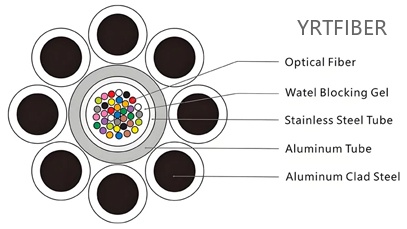
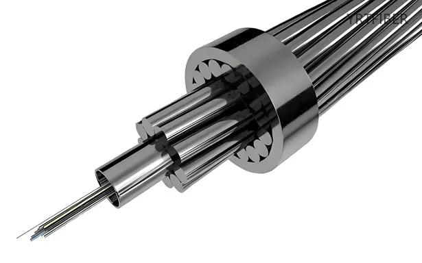
OPGW (Optical Ground Wire) Structure: Multiple optical fibers are placed inside a stainless steel tube filled with water-blocking gel for sealing, moisture protection, and cushioning. This stainless steel tube is then wrapped with an aluminum tube (forming the "aluminum-covered stainless steel tube" structure), which enhances short-circuit current capacity thanks to aluminum's excellent conductivity and corrosion resistance. Finally, the aluminum-covered stainless steel tube is stranded together with aluminum clad steel wires, which provide high mechanical strength and fulfill the electrical and lightning protection requirements of an overhead ground wire. This composite design enables OPGW to serve three functions simultaneously: ground wire protection, high fault current carrying, and optical fiber communication.
Beneficios de OPGW Aluminum-Covered Stainless Steel Tube Fiber Cable
1. High-Quality Design, Materials & Fiber Protection
Compliant with IEC60794 and IEEE1138 standards, manufactured with Grade A materials, and featuring a sealed stainless steel tube that provides superior protection for optical fibers against moisture, lightning, and extreme environmental conditions – ensuring long-term reliability.
2. Engineering Support, Accessory Hardware & Application Scope
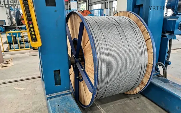
Includes full engineering supervision and its own line of accessory hardware. Since OPGW installation requires a power outage (causing significant losses), it is primarily used for new high-voltage lines above 110kV as well as for the transformation of existing old lines.
Aplicaciones de Ingeniería OPGW Aluminum-Covered Stainless Steel Tube Fiber Cable
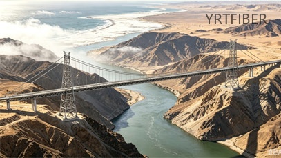
1. Extreme Climate and High-Altitude Transmission Lines
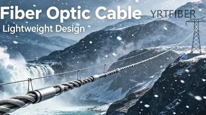
Under severe conditions such as repeated icing and large temperature differences, OPGW optical cable can withstand continuous stress and deformation, ensuring stable fiber transmission. It can also integrate sensing technology to monitor icing and swaying risks in real time, providing reliable protection for transmission corridors in harsh environments.
2. Transmission Projects in Highly Corrosive Environments
In highly corrosive environments such as coastal mudflats and chemical industrial parks, the aluminum-clad stainless steel tube structure eliminates electrochemical corrosion conditions, allowing long-term resistance to salt spray and chemical erosion without anti-corrosion grease. The aluminum cladding also enhances short-circuit current carrying capacity, making it especially suitable for offshore wind power transmission and power lines in chemical plant areas.

3. Smart Grid and New Energy Integration Communication
This optical cable, as the main carrier for power communication backbones, can utilize remaining fiber cores to build a hybrid communication architecture that addresses public network blind spots during inspection data transmission. It also supports ultra-long-distance, high-bandwidth transmission, meeting data needs for online monitoring, drone video, and more, providing the fiber optic foundation for the digital transformation of power systems.
Envío y embalaje
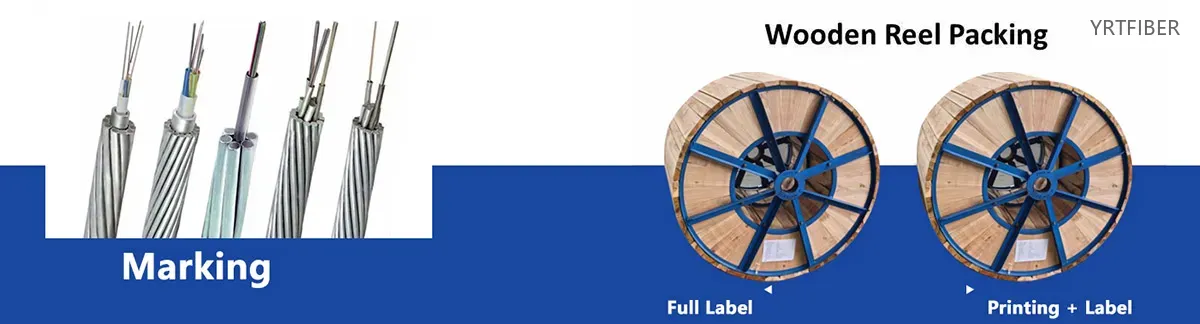
Packaging Requisitos:
- 1: Todos los cables se enrollarán en carretes de madera tratados que no se puedan devolver
- 2: Los extremos del cable deben estar firmemente asegurados al carrete y protegidos con waterproof tapas retráctiles
- 3: Cada carrete debe incluir:
Una capa exterior protectora de envoltura de plástico
Refuerzo de listones de madera para garantizar la estabilidad.
Al menos 1 metro de extremo de cable libre reservado para pruebas
Una longitud de carrete estándar de 3000 mm (con una tolerancia permitida de ± 2%)
Identificación del cable:
La chaqueta exterior debe mostrar:
- 1, Numeración secuencial única cada 1m (+ 1% de varianza permitida)
- 2, Marcas adicionales repetidas a intervalos de 1 m que muestran:
Código de producto y recuento de fibra
Identificación del fabricante
Fecha de producción (mes / año)
Longitud total del cable
Standard Dimensiones del embalaje:
| Length | Container | Size (L×W×H) | Net Mass | Total Mass |
|---|---|---|---|---|
| 2 km | Carrete de madera | 90 × 75 × 90 cm | 156 kg | 220 kg |
| 3 km | Carrete de madera | 100 × 68 × 100 cm | 240 kg | 280 kg |
| 4 km | Carrete de madera | 109 × 75 × 109 cm | 300 kg | 368 kg |
| 5 km | Carrete de madera | 129 × 72 × 129 cm | 400 kg | 480 kg |
Technical Referencia:
- 1, diámetro del cable estándar: 10,0 mm
- 2, Distancia máxima de span: 100 m
- 3, Póngase en contacto con el equipo de ventas para obtener especificaciones técnicas completas.
Estándares de marcado de carrete:
Las marcas permanentes (altura mínima de 25-30 mm) deben aparecer en ambos lados de cada carrete:
- 1 。 Nombre de la empresa y marca registrada
- 2, Longitud del cable incluida
- 3, Especificaciones del cable (tipo / recuento de fibra)
- 4, Orientación de bobinado
- 5, Medidas de peso (bruto / neto)
Nota: Todos los materiales de embalaje de madera deben someterse a un tratamiento de fumigación adecuado antes de su uso.
Comparación de productos:
Al‑covered Stainless Steel Tube OPGW vs Standard Stainless Steel Tube OPGW
| Feature / Dimension | Al‑covered Stainless Steel Tube OPGW (Central Type) | Standard Stainless Steel Tube OPGW (Stranded/Layer Type) |
|---|---|---|
| Structural Features | Optical fibers are placed in a seamless stainless steel tube (filled with water‑blocking gel). The stainless steel tube is then encased in a layer of aluminum (aluminum‑clad), and the entire assembly is stranded with single or double layers of aluminum‑clad steel (ACS) wires and/or aluminum alloy wires. | Optical fibers are placed in a seamless stainless steel tube (filled with water‑blocking gel). The stainless steel tube (optical unit) replaces one or more metal wires in the stranded layer, and is surrounded by layers of ACS wires and/or aluminum alloy wires. |
| Fiber Core Capacity (typical) | Up to 48 cores (central tube design, outer diameter approx. 5.2 mm). | Up to 288 cores (stranded design can accommodate up to 3 optical units). |
| Typical Applications | Extremely corrosive environments: coastal areas, chemical plants, heavy industrial zones with salt spray. Transmission lines requiring high fault current capacity (short‑circuit) and lightning resistance, as well as small diameter and low weight constraints. | All power transmission lines (35 kV to 1100 kV). Particularly suited for long‑span routes (e.g., river crossings), high‑voltage backbones, and applications requiring excellent heat resistance during short‑circuit events. |
| Engineering Pros | ① Excellent galvanic corrosion resistance: the aluminum cladding is in direct contact with the outer ACS wires, with no potential difference – no anti‑corrosion grease required. ② Increased fault current capacity: the aluminum layer increases the conductive cross‑section, boosting short‑circuit capacity by 10–20 %. ③ Good anti‑corrosion performance: suitable for severely corrosive service environments. ④ Fully metallic structure – long service life, high reliability. | ① High short‑circuit temperature tolerance: up to 450 °C (compared to <300 °C for aluminum tube types). ② Good insulation: stainless steel has high resistance and does not conduct current – during short‑circuit events, heat is transferred from adjacent wires, keeping the stainless steel tube relatively cool and protecting optical fibers. ③ High fiber capacity: stranded design supports up to 288 fibers. ④ Good mechanical compatibility: both structure and span‑tension characteristics are similar to conventional ground wires, making replacement easy. |
| Engineering Cons | ① Lower high‑temperature tolerance: the aluminum cladding tends to experience irreversible plastic deformation above 200 °C. ② Smaller fiber capacity: the central tube structure typically accommodates ≤48 fibers. ③ Higher cost per fiber for lower fiber counts. ④ Stricter fiber excess length control: relies solely on internal tube slack, with no secondary slack from stranding. | ① Galvanic corrosion risk: contact between stainless steel and ACS wires can create a potential difference – anti‑corrosion grease is required to fill the gaps. ② Complex structure: multiple stranding layers increase weight and manufacturing difficulty. ③ Larger cable diameter and heavier weight, leading to higher wind and ice loads. |
| Corrosion / Moisture Resistance | Excellent. The aluminum cladding is in direct contact with the outer ACS wires – no potential difference, so no galvanic corrosion occurs, and no anti‑corrosion grease is required. Well suited for coastal and chemical zones. | Good, but anti‑corrosion grease is required to fill the gaps between the stainless steel tube and ACS wires to prevent galvanic corrosion. Grease may degrade under long‑term exposure, requiring periodic inspection. |
| Short‑circuit Temperature Tolerance | Moderate. The aluminum layer conducts current, contributing to the cable’s overall conductivity, but tends to deform irreversibly above 200 °C. | Excellent (up to 450 °C). Stainless steel has high resistivity – it does not conduct current, and during short‑circuits, heat is transferred from adjacent wires, keeping the steel tube relatively cool and protecting optical fibers. |
| Fault Current / Lightning Resistance | Excellent. The aluminum cladding increases the conductive cross‑section of the tube, improving fault current and lightning resistance. Suitable for transmission lines requiring small diameter and high fault current capacity. | Good. Fault current capacity is determined by the cross‑section of the ACS and aluminum alloy wires. The stainless steel tube contributes negligibly to conductivity. |
| Cost (Relative) | Medium (Al‑covered tube requires additional aluminum cladding, but no expensive anti‑corrosion grease is needed; reduces long‑term maintenance and grease application costs). | Medium‑Low (Lower core count: stainless steel tube has higher manufacturing cost; Higher core count: stranded design offers lower cost per fiber). |
| Maintenance Difficulty | Low – no anti‑corrosion grease required; corrosion resistance reduces maintenance frequency; central structure simplifies construction. | Medium – anti‑corrosion grease may need periodic inspection, and aged grease must be cleaned and reapplied during mid‑span repairs. |
| Suitable Voltage Level (typical) | 35 kV – 220 kV (suitable for medium to high voltage transmission lines where corrosion is a concern). | 35 kV – 1100 kV (including 500 kV and 1000 kV ultra‑high voltage backbones). |
| Lifespan / Durability | 30+ years (no grease degradation issues; superior corrosion resistance). | 30+ years (grease may degrade over time, but stainless steel tube remains intact). |
OPGW Aluminum-Covered Stainless Steel Tube Fiber Cable Guía de selección
Choose Al‑covered Stainless Steel Tube OPGW when:
The transmission line passes through severely corrosive environments such as coastal areas, chemical industrial zones, or heavy salt‑spray regions. This design eliminates galvanic corrosion concerns because the aluminum cladding is in direct contact with the outer ACS wires, with no potential difference, so no anti‑corrosion grease is required. It is also well suited for applications requiring high fault current capacity – the aluminum layer increases the conductive cross‑section, typically boosting short‑circuit capacity by 10–20 %. For lines with tight diameter or weight constraints, this design is advantageous due to its single‑layer construction, small diameter, and low weight. Typical voltage levels for this cable range from 35 kV to 220 kV, but it can also be applied on higher voltage lines when corrosion resistance is a primary requirement.
Choose Standard Stainless Steel Tube OPGW (Stranded Type) when:
High fiber count (up to 288 cores) is required – the stranded design can accommodate up to three optical units. For transmission lines demanding excellent short‑circuit temperature tolerance (up to 450 °C), this design is preferred over aluminum‑covered alternatives. It is also the dominant choice for ultra‑high voltage backbones (500 kV to 1100 kV), where long spans, high mechanical strength, and thermal stability are critical. Additionally, for lines that require replacement of conventional ground wires, this design offers good mechanical compatibility and similar span‑tension characteristics, simplifying retrofitting.
Corrosion management considerations:
For Al‑covered designs, galvanic corrosion is inherently prevented without anti‑corrosion grease, making it particularly suitable for long‑term operation in harsh environments with minimal maintenance. For standard designs, anti‑corrosion grease is required to fill the gaps between the stainless steel tube and ACS wires; the grease may degrade over time and requires periodic inspection.
Core count and cost trade‑offs:
For low to medium fiber counts (48 cores or less), Al‑covered designs often achieve lower total lifecycle cost due to corrosion resistance and grease‑free construction. For high fiber counts (above 48 cores), stranded stainless steel designs offer better economy and flexibility, with lower cost per fiber and proven performance on numerous high‑voltage backbones.
Aluminum-Covered Stainless Steel Tube OPGW – Short Installation Guide
1. Pre-installation check:Inspect the cable reel for shipping damage. Measure fiber attenuation with an OTDR and compare with factory test report.
2. Hardware mounting:Install OPGW suspension clamps and dead-end fittings as per tower design. Use corona rings and anti-vibration devices (spiral dampers or Armor Rods) where required for high-voltage lines.
3. Stringing:Place the reel on a tension-controlled stand. Pull the cable using a pulling grip and swivel, keeping tension ≤20% of the cable’s rated tensile strength (RTS). Maintain minimum bending radius: ≥30× cable diameter during pulling.
4. Sag adjustment:Set sag according to the design sag‑tension table for the specific span and temperature. Use a dynamometer or laser rangefinder for accurate measurement.
5. Clamping & grounding:Secure the cable with permanent dead-end or suspension clamps. Connect the aluminum‑covered steel tube and outer wires to the tower ground at specified intervals (typically every 200–300 m) using proper grounding clamps and conductor.
6. Fiber splicing:Splice the stainless steel tube optical unit at joint boxes. Ensure the tube is properly sealed against moisture. Perform OTDR acceptance testing after splicing.
7. Final inspection:Check all hardware for tightness, verify ground continuity, and document sag values for future reference.
Key points: No anti‑corrosion grease is required on the aluminum‑covered tube; the aluminum cladding eliminates galvanic corrosion with ACS wires. Keep the cable clean and avoid damage to the aluminum layer during handling.
Descarga el catálogo de productos de YRTFIBER
Disparo Real De Fábrica
Cable Sheathing
Loose tubes, strength members, and filler ropes are stranded at controlled pitches to form the cable core. The core is then extruded with a PE or LSZH outer sheath. For armored types, steel strips are applied before a second extrusion pass. The sheathing line includes a diameter measurement and cooling system to guarantee a uniform, smooth finish.
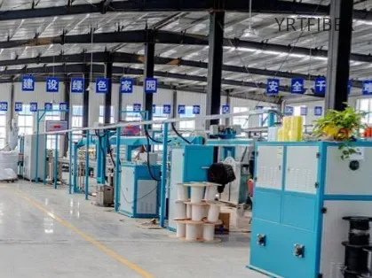
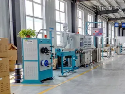
Loose Tube Extrusion Line
Colored optical fibers are fed into the extrusion line, where they are enclosed in PBT or PE loose tubes. The tubes are simultaneously filled with water‑blocking gel to protect the fibers from moisture.
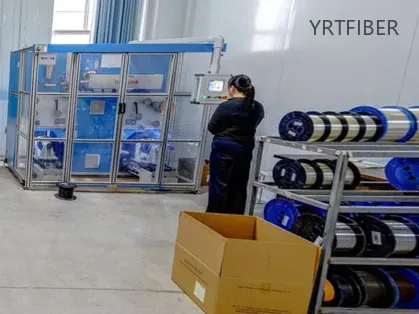
Quality Control Laboratory
Routine tests include tensile strength, crush resistance, temperature cycling, and water penetration. These ensure that every cable meets industry standards for mechanical and environmental performance.
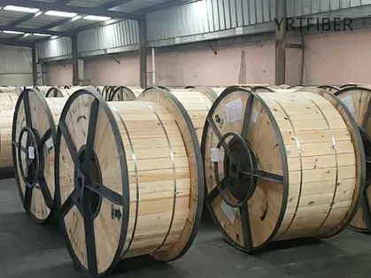
Final Coiling & Packaging Zone
Finished cables are precisely wound onto wooden or steel reels. The reels are wrapped with protective materials and labeled for shipment, ensuring safe transport and easy identification.
Preguntas Frecuentes y Consulta Rápida
OPGW Aluminum-Covered Stainless Steel Tube Fiber Cable FAQ
1. ¿Qué hace que OPGW-4 sea diferente de otros tipos de cables OPGW?
OPGW-4 utiliza un tubo suelto central de acero inoxidable que es aluminum-covered, que combina alta mechanical resistencia, protección térmica y lightweight conductividad, lo que lo hace adecuado para long-span torres de transmisión de alto voltaje.
2. ¿Es este cable adecuado para áreas con de rayos y alta EMI?
Sí. El diseño cubierto de aluminio proporciona excellent capacidad de conexión a tierra, mientras que el stainless tubo de acero protege las fibras ópticas de la interferencia electromagnética (EMI), asegurando la integridad de la señal incluso en corredores de servicios públicos hostiles.
3. ¿Cuáles son las especificaciones de fibra disponibles?
OPGW-4 admite 12 a 144 núcleos, utilizando G.652D (estándar SMF) o G.655C (NZDSF), lo que ofrece flexibilidad para los sistemas de utilidad SCADA, protección y telecomunicaciones.
4. ¿Cómo se instala el cable en las líneas de transmisión?
Está instalado como el cable de tierra superior en torres de transmisión utilizando abrazaderas de tensión, empuñaduras sin salida y accesorios de suspensión. Su función dual (conexión a tierra + datos) reduce los costos de material y mantenimiento.
5. ¿Cuáles son los casos de uso típicos para OPGW-4?
OPGW-4 es ampliamente utilizado en:
220kV y líneas de transmisión de alto voltaje superiores
Red inteligente y sistemas SCADA
Electrical subestaciones
Control remoto y comunicación de protección
Envíe Su Consulta
Rellene el siguiente formulario y nos pondremos en contacto con usted en un plazo de 24 horas.


