

 Español
 Português
 لالعربية
 Русский
 Bahasa Indonesia
 Français
 Türkçe
 Bahasa Melayu

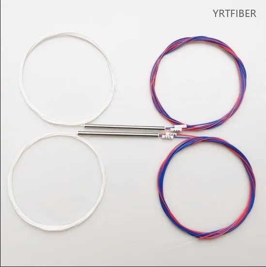
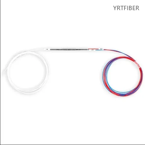
1×2 FBT Fiber Optic Splitter – Single‑mode Bare Fiber G652D/G657A
1×2 splitting configuration for equal optical division.
Uses single‑mode G652D/G657A fiber for low-loss, long-distance transmission.
Bare fiber termination for fusion splicing.
Low insertion loss and high uniformity for stable performance.
Rugged design, suitable for telecom and FTTx deployments.
What is a 1×2 FBT Fiber Optic Splitter?
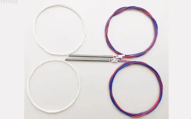
A 1×2 FBT Fiber Optic Splitter is a device designed for single - mode transmission with G652D or G657A fiber, having a 1×2 splitting configuration, bare fiber terminations, and offering telecom - grade performance for efficient signal distribution in fiber networks.
1×2 FBT Fiber Optic Splitter Specification parameters
- Specification parameters
- OPTICAL CHARACTERISTICS
| Coupling Ratio | Insertion Loss | |
|---|---|---|
| Premium | A Grade | |
| 40/60 | 4.7 / 2.7 | 5.0 / 2.9 |
| 30/70 | 6.0 / 1.9 | 6.4 / 2.1 |
| 20/80 | 7.9 / 1.2 | 8.4 / 1.4 |
| 10/90 | 11.3 / 0.5 | 12.7 / 0.8 |
| 5/95 | 15.2 / 0.4 | 18.5 / 0.5 |
| 1/99 | 22.5 / 0.3 | 23.0 / 0.4 |
Product Structure & Composition
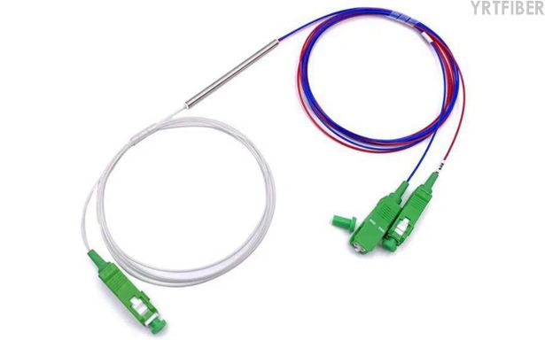
The 1×2 FBT Fiber Optic Splitter is based on the fused biconical taper (FBT) technology. The single - mode G652D or G657A fibers are fused and tapered to create the splitting function. The input fiber is split into two output fibers in a 1×2 configuration. The bare fiber terminations at both input and output sides are designed for seamless fusion splicing with other fibers in the network. This design ensures a continuous and low - loss optical path.
Benefits of 1×2 FBT Fiber Optic Splitter
Equal Optical Division
The 1×2 splitting configuration of this splitter ensures equal distribution of optical power between the two output fibers. This is crucial for maintaining consistent signal strength in different branches of the fiber network, enabling reliable data transmission.
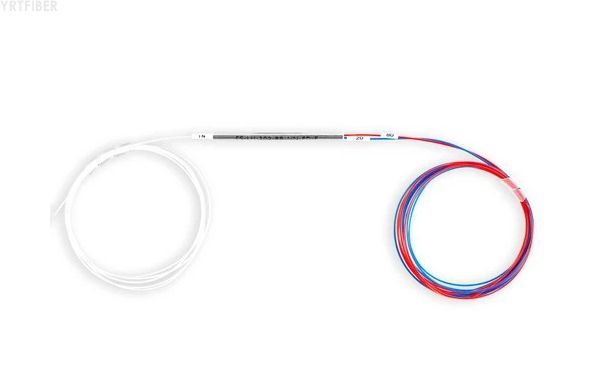
Low - loss and Long - distance Transmission
By using single - mode G652D or G657A fibers, the splitter achieves low - loss and long - distance transmission capabilities. These fibers are optimized for minimizing signal attenuation, making the splitter suitable for large - scale telecom and FTTx networks.
Engineering Applications 1×2 FBT Fiber Optic Splitter

Telecom Networks
In telecom networks, the 1×2 FBT Fiber Optic Splitter is used to distribute optical signals from a central source to multiple end - users or different network segments. Its low - loss and long - distance transmission features make it ideal for covering large geographical areas.

FTTx Deployments
For Fiber - to - the - x (FTTx) deployments, including FTTH (Fiber - to - the - Home), FTTB (Fiber - to - the - Building), etc., the splitter plays a vital role in splitting the optical signal to individual subscribers. Its bare fiber terminations are convenient for fusion splicing in the field, facilitating the construction of the FTTx infrastructure
Shipping & Packaging
Please contact the sales manager for specific shipping costs
Product Comparison:
1×2 FBT Splitter VS 1×2 PLC Splitter VS 1×4 FBT Splitter
| Feature / Dimension | 1×2 FBT Splitter | 1×2 PLC Splitter | 1×4 FBT Splitter |
|---|---|---|---|
| Technology | Fused Biconical Taper (FBT) - fibers fused and stretched together | Planar Lightwave Circuit (PLC) - waveguide on silica chip | Fused Biconical Taper (FBT) - cascaded from 3 × 1×2 stages |
| Split Ratio Flexibility | Customizable: 50/50, 40/60, 30/70, 20/80, 1/99 | Fixed symmetrical: 50/50 only (for 1×2) | Customizable: same as 1×2 FBT, but cascaded |
| Insertion Loss (typical 50/50) | ≤ 3.5 - 4.0 dB | ≤ 3.5 - 4.0 dB (similar for 1×2) | ~7.0 - 8.0 dB (cascaded from 3 × 1×2) |
| Split Uniformity | Good for 1×2 (±0.5 dB typical) | Excellent (±0.3 dB typical) | Poor - uniformity degrades as split ratio increases |
| Wavelength Range | Narrow band - single/dual/triple window only (e.g., 1310/1490/1550 nm) | Full band - 1260 to 1650 nm | Narrow band - same as 1×2 FBT |
| Polarization Dependent Loss (PDL) | 0.1 - 0.15 dB (single stage) | < 0.2 dB | ≤ 0.45 dB (cascaded from 3 stages) |
| Temperature Dependent Loss (TDL) | ±0.15 dB (-5 to 75°c) | ±0.15 dB (-5 to 75°c) | ±0.45 dB (cascaded effect) |
| Operating Temperature | -5°c to +75°c (standard) | -40°c to +85°c | -5°c to +75°c (standard) |
| Device Size (1×2) | Compact - ~55mm × 3.2mm (bare) | Very compact - ~40mm × 4mm (bare) | Larger - cascaded construction increases footprint |
| Package Types | Steel tube, ABS box, bare fiber | ABS box, LGX cassette, steel tube, micro | Steel tube, ABS box |
| Relative Cost | Lowest - economical for 1×2 | Medium - higher than FBT for small ratios | Medium - cascaded construction increases cost |
| Typical Applications | CATV tapping, test equipment, small networks, custom ratio splitting | FTTH/PON, data centers, WDM networks | Small distribution networks (≤8 ports) |
1×2 FBT Fiber Optic Splitter Selection Guide
Choose the 1×2 FBT Splitter when:
Custom split ratios are required - FBT supports asymmetric ratios like 70/30. 80/20. or 90/10. PLC only offers fixed 50/50 for 1×2. This is critical in CATV networks where tapping a small portion of signal for monitoring is common.
Budget is the primary constraint - For 1×2 splitting, FBT is the most cost-effective option.
The operating environment is controlled - FBT operates reliably within -5°c to +75°c. For indoor equipment rooms, labs, or temperature-stable enclosures, this is sufficient.
Wavelength requirements are narrow - If the network uses only 1310nm, 1490nm, or 1550nm wavelengths, FBT performs well.
Low port count is needed - For simple 1×2 splitting with minimal signal distribution requirements.
Choose the 1×2 PLC Splitter when:
Wide temperature range is required - PLC operates from -40°c to +85°c. For outdoor cabinets, pole-mounted enclosures, or desert/arctic deployments, PLC is the reliable choice.
WDM or multi-wavelength operation is planned - PLC supports the full 1260-1650nm range, essential for CWDM/DWDM networks where multiple wavelengths share the same fiber.
Long-term reliability is critical - PLC has better environmental stability and lower failure rates in harsh conditions.
Future scalability is anticipated - If the 1×2 splitter may later be replaced with higher-count splitters (1×8. 1×16. 1×32), standardizing on PLC from the start simplifies inventory management.
Avoid the 1×4 FBT Splitter when:
Signal uniformity is important - 1×4 FBT is cascaded from three 1×2 stages, resulting in up to 3dB uniformity variation. This means some outputs receive significantly less power than others.
Wide temperature operation is needed - TDL cascades to ±0.45dB, making performance less stable across temperature changes.
Compact size is required - Cascaded construction increases device footprint.
Engineering Best Practices:
Do not mix FBT and PLC in cascaded networks - Insertion loss inconsistencies cause signal degradation.
For 1×2 splitting in greenfield FTTH/PON deployments, many engineers now default to PLC even for 1×2 to maintain consistency with higher-count PLC splitters elsewhere in the network.
For test and measurement applications, FBT’s customizable ratios and low cost make it the preferred choice for lab setups and monitoring taps.
When deploying outdoors, always verify the splitter's temperature rating matches the local climate. FBT's -5°c lower limit may be inadequate for cold regions.
| Decision Factor | 1×2 FBT | 1×2 PLC | 1×4 FBT |
|---|---|---|---|
| Best for custom ratios | ✓✓ | ✗ | ✓ |
| Best for wide temperature | ✗ | ✓✓ | ✗ |
| Best for budget | ✓✓ | ✓ | ✗ |
| Best for uniformity | ✓ | ✓✓ | ✗ |
| Best for WDM | ✗ | ✓✓ | ✗ |
Fusion Splicing Preparation
Fusion Splicing Preparation
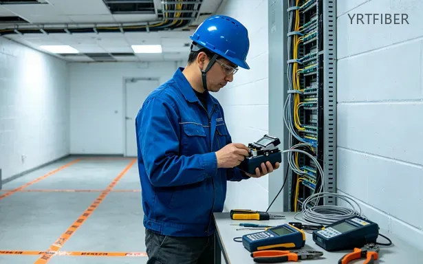
Prepare the single - mode fibers to be connected to the 1×2 FBT Fiber Optic Splitter. Strip the outer coating of the fibers, clean the fiber cores with alcohol, and use a fiber cleaver to create a clean, perpendicular cut at the end of each fiber.
Fusion Splicing Process
Insert the bare fiber terminations of the splitter and the prepared fibers into the fusion splicer. Align the fibers accurately within the splicer according to the device's instructions. Then, initiate the fusion process, which will melt and join the fibers together, creating a low - loss connection.
Testing after Installation
After fusion splicing, use an optical power meter to measure the insertion loss and check the uniformity of the splitter. Compare the measured values with the specified parameters of the splitter. If the values are outside the acceptable range, re - check the fusion splices and ensure proper fiber alignment.
Download YRTFIBER Product Catalog
Factory Real Shot
Frequently Asked Questions & Quick Inquiry
1×2 FBT Fiber Optic Splitter FAQ
Q1: What is a 1×2 FBT optical splitter?
A1: A fiber splitter using fused biconical taper technology that splits one input into two outputs, commonly used in telecom and FTTx networks.
Q2: What fiber types are supported?
A2: Supports single‑mode optical fibers G652D or G657A for stable and efficient transmission.
Q3: Why are bare fiber terminations used?
A3: Bare fiber ends are provided for fusion splicing, offering flexibility in custom installations and reduced connector loss.
Q4: Where can this splitter be applied?
A4: Ideal for FTTH deployments, telecom fiber distribution, patch panels in ODFs, and fiber optic testing setups.
Q5: Is this splitter suitable for high-density network systems?
A5: Yes, due to its simple 1×2 configuration and bare fiber interface, it's flexible for telecom central offices and fiber cabinets.
Can the 1×2 FBT Fiber Optic Splitter be used with multi - mode fiber?
No, this splitter is specifically designed for single - mode G652D or G657A fiber and is not suitable for multi - mode fiber applications.
How do I connect the 1×2 FBT Fiber Optic Splitter to other fibers?
The splitter has bare fiber terminations, so you need to use fusion splicing techniques to connect it to other single - mode fibers in the network.
What is the typical lifespan of the 1×2 FBT Fiber Optic Splitter?
Due to its rugged design, with proper installation and maintenance, it can have a lifespan of over 10 years in telecom and FTTx environments.
Send Your Inquiry
Fill out the form below and we'll get back to you within 24 hours.


