

 Español
 Português
 لالعربية
 Русский
 Bahasa Indonesia
 Français
 Türkçe
 Bahasa Melayu

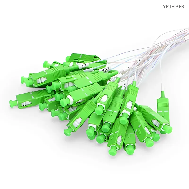
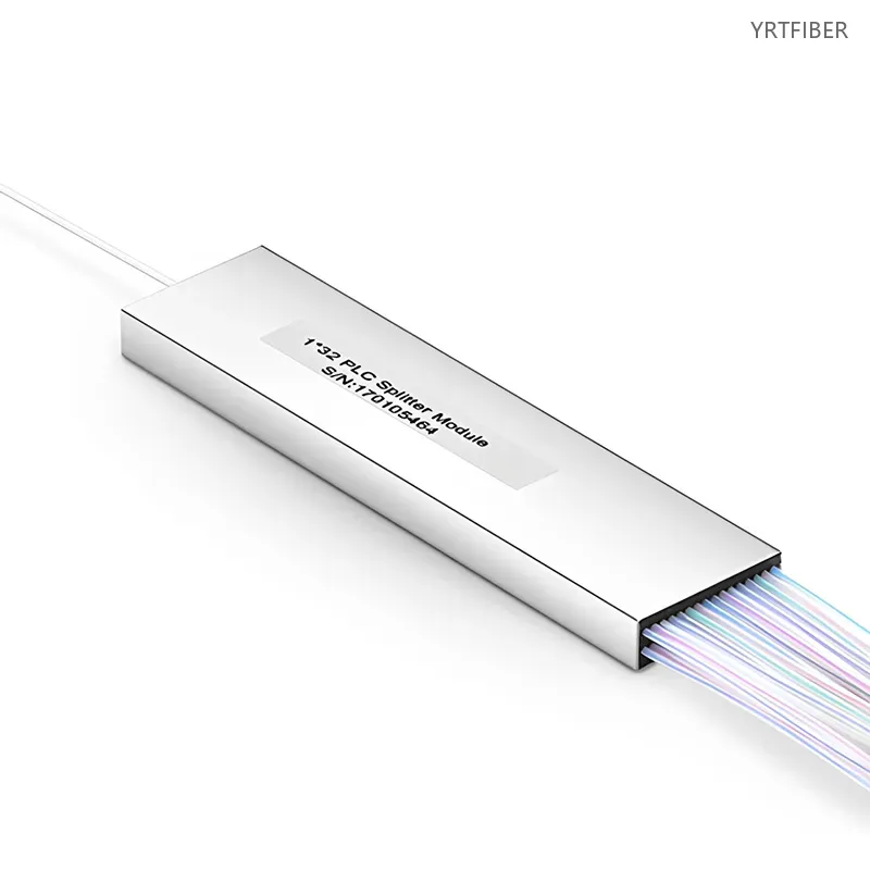
1×32 PLC Fiber Optic Splitter – Mini Module with SC/UPC or SC/APC Connectors
1×32 configuration, expanding from one input to 32 independent channels.
Low insertion loss and high return loss optimize signal quality and link stability.
Mini-module form factor, significantly saving rack and cabling space.
SC interface (supports UPC/APC), seamlessly integrating into mainstream network systems.
Compatible with single-mode fiber (G652D, G657A), meeting long-distance transmission requirements.
What is a 1×32 PLC Fiber Optic Splitter?
A 1×32 PLC fiber optic splitter is a device with a mini - module structure and SC (UPC/APC) interfaces, designed for high - density cabling in FTTx, LAN, and telecom networks. It splits one input into 32 channels, offers optimal signal performance, saves space, and is compatible with specific single - mode fibers.
1×32 PLC Fiber Optic Splitter Specification parameters
- Specification parameters
- OPTICAL CHARACTERISTICS
| Package Style | Mini Module | Polarization Dependent Loss | ≤ 0.3dB |
| Distribution Type | 1x32 | Insertion Loss with Connectors | ≤ 16.9dB |
| Technology Type | PLC (Planar Lightwave Circuit) | Return Loss | ≥ 55dB |
| Connector Type (Input & Output) | SC/APC | Uniformity | ≤ 1.5dB |
| Fiber Type | G.657A1 | Directivity | ≥ 55dB |
| Fiber Mode | Singlemode | Temperature Dependent Loss | ≤ 0.5dB |
| Split Ratio | Symmetrical | Wavelength Dependent Loss | ≤ 0.3dB |
| Input/Output Fiber Length | 1.5m | Input/Output Fiber Diameter | 2.0mm |
| Relative Humidity | 45%~75% | Operating Bandwidth | 1260~1650nm |
| Maximum Input Power | 300mW | Reliability Compliance | GR-1221/1209 |
| Dimensions (HxWxD) | 0.24"x3.15"x0.79" (6x80x20mm) | Temperature | Operating -40 to 85°C (-40 to 185°F), Storage -40 to 85°C (-40 to 185°F) |
Product Structure & Composition
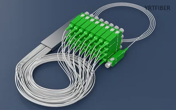
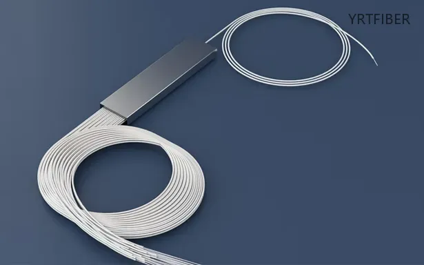
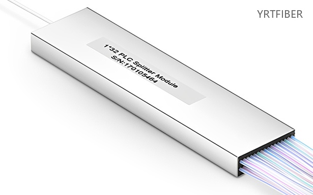
This 1×32 PLC splitter evenly distributes optical signals from one input to 32 outputs. It features SC connectors with UPC (general low‑loss) or APC (high return loss for long‑haul) polish. A compact mini‑module housing protects the internal components and saves installation space.
Benefits of 1×32 PLC Fiber Optic Splitter
High - density Expansion
The 1×32 configuration enables large - scale port expansion. In networks such as FTTx, where multiple end - users need to be connected from a single source, this splitter provides an efficient solution. It allows for the distribution of optical signals to a large number of users or network devices without the need for multiple splitters, reducing complexity and cost.
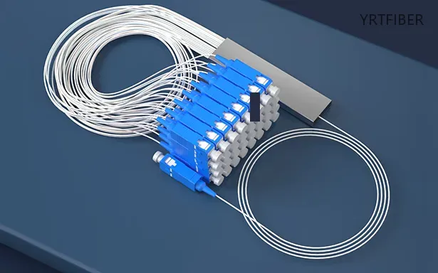
Excellent Signal Quality
With low insertion loss and high return loss, the splitter optimizes signal quality. Low insertion loss ensures that the optical signal loses minimal power as it passes through the splitter, while high return loss prevents signal reflections that could degrade the overall signal quality. This results in stable and reliable optical links, which is essential for high - speed data transmission.
Space - saving
The mini - module form factor is a significant advantage, especially in data centers, central offices, or other network installations where space is limited. The compact design allows for more splitters to be installed in a single rack, maximizing the use of available space and facilitating neater cabling arrangements.
Engineering Applications 1×32 PLC Fiber Optic Splitter

1. Mass FTTH / FTTx Deployment
In FTTH networks, the 1×32 PLC splitter is positioned as a single‑stage centralized splitter within an optical distribution frame or street cabinet, dividing a single GPON/EPON feeder fiber into 32 subscriber drops. Because each PON port serves exactly 32 end users, the splitter aligns with standardized optical budgets (≈16.5-17 dB insertion loss) and simplifies future upgrades, making it ideal for residential deployment from multi‑dwelling units to rural clusters.
In this application, the splitter operates without power, ensuring high reliability and low maintenance in the outside plant.
2. Central Office & Remote Node Splitting
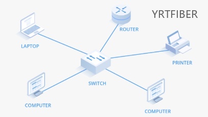
In a centralized PON architecture, the 1×32 splitter is installed inside an optical distribution hub or street‑side cabinet, converting high‑capacity feeder transmission into customer‑facing access distribution. Because these sites are physically confined and often exposed to outdoor environments, the splitter must maintain low insertion loss, excellent uniformity (<1.5 dB) and wide‑temperature operation (-40°C to +85°C) to ensure stable service across the entire coverage area.
The compact form factor (LGX cassette or rack‑mount) allows easy integration into standard 19‑inch racks, reducing feeder fiber counts and active equipment.

3. Enterprise Campus & CCTV Monitoring Networks
For campus backbone networks or large‑scale surveillance systems, a 1×32 PLC splitter distributes one optical uplink to 32 camera nodes or remote switches, greatly reducing feeder fiber counts and eliminating powered splitters. In non‑uniform scenarios such as security monitoring, engineers can also use customized splitting ratios (e.g., 70:30) to allocate more bandwidth to critical observation points while still leveraging the PLC chip's low loss and high uniformity for consistent image transmission.
This passive approach minimizes points of failure and lowers long‑term operational costs.
Shipping & Packaging

Product Comparison:
1×32 PLC Fiber Optic Splitter vs 1×16 PLC Fiber Optic Splitter
| Feature / Dimension | 1×32 PLC Fiber Optic Splitter | 1×16 PLC Fiber Optic Splitter |
|---|---|---|
| Splitting Configuration | 1×32, expanding to 32 channels | 1×16, expanding to 16 channels |
| Insertion Loss | Generally slightly higher due to more channels, but still low for reliable operation | Lower compared to 1×32 as there are fewer channels |
| Space Occupancy | Mini - module, but may occupy slightly more space due to more output ports | Mini - module, occupies less space than 1×32 |
| Application Focus | Suitable for large - scale port expansion in high - density networks like large FTTx projects or big data centers | Ideal for smaller - scale port expansion in medium - sized LANs or less - dense telecom network segments |
| Connector and Fiber Compatibility | SC (UPC/APC) interface, compatible with G652D/G657A single - mode fiber | SC (UPC/APC) interface, compatible with G652D/G657A single - mode fiber |
1×32 PLC Fiber Optic Splitter Selection Guide
When choosing between a 1×32 and a 1×16 PLC fiber optic splitter, consider the scale of your network expansion needs. If you are working on a large - scale project such as a large FTTx deployment, a big data center, or a major telecom network expansion where you need to connect a large number of users or devices, the 1×32 splitter is the better choice. It offers the necessary high - density port expansion.
However, if your network is of a medium - size, such as a medium - sized office LAN or a less - dense telecom network segment where the number of connections required is relatively small, the 1×16 splitter may be more appropriate. It provides a more cost - effective and space - efficient solution for smaller - scale port expansion.
Parameter - Best Fit
| Parameter | Best Fit |
|---|---|
| Large - scale port expansion in high - density networks | 1×32 PLC Fiber Optic Splitter |
| Smaller - scale port expansion in medium - sized networks | 1×16 PLC Fiber Optic Splitter |
| FTTx projects with a large number of end - users | 1×32 PLC Fiber Optic Splitter |
| Medium - sized LANs with limited connection requirements | 1×16 PLC Fiber Optic Splitter |
Mixed deployment guidance:
In a large - scale network with a mix of high - density and medium - density areas, a combination of 1×32 and 1×16 splitters can be used. 1×32 splitters can be deployed in areas where a large number of connections are needed, such as in the main distribution areas of an FTTx network. 1×16 splitters can be used in areas with fewer connection requirements, like in smaller sub - networks or for connecting a limited number of devices in a specific area of a data center. This approach optimizes cost - effectiveness and space utilization.
Installation Instructions
Pre - installation Inspection
Visually check the 1x32 PLC fiber optic splitter. Examine the mini - module housing for any signs of damage, such as cracks or dents. Check the SC connectors; the ferrules should be clean, and the UPC/APC polish should be free from scratches. Ensure that the labeling on the input and output ports is clear.
Connection
Connect the single - mode fiber (G652D or G657A) to the input port of the splitter. Align the key on the SC connector with the keyway of the input port and insert the connector firmly until it locks.
For the output ports, connect the fibers to the respective SC connectors in the same way. Make sure to label each output connection clearly for easy identification.
Mounting
Mount the splitter in the patch panel or ODF. Use the appropriate mounting hardware provided to secure the splitter in place. Ensure that the splitter is properly positioned and does not cause any strain on the connected fibers.
Testing
Use an optical power meter to measure the insertion loss at each output port. Compare the measured values with the specified insertion loss of the splitter. If the measured values are significantly higher, re - check the connections, clean the connectors if necessary, and inspect the splitter for any internal damage. Also, check the return loss to ensure it meets the specified standards.

Download YRTFIBER Product Catalog
Factory Real Shot
State-of-the-Art Manufacturing Facilities
Our 60,000 sqm dust-proof workshop houses over 21+ automated production lines for single-core and MPO patch cords. Equipment includes high-precision fiber cutters (±0.08 mm tolerance), FLC automatic termination machines, and UV curing systems, enabling a daily output of thousands of connectors with consistent quality.
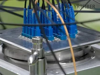
Precision Core Manufacturing Process
The process starts with micro-tolerance cutting (end-face angle ±0.5°) and six-axis fusion splicing (core deviation ≤1 μm). After multilayer jacketing with LSZH, PVC, or OFNP, connectors are polished on automated lines for PC, UPC, or APC finishes, achieving up to 7,000 connectors per 11-hour shift.

Rigorous Quality Assurance & Testing
Every patch cord undergoes 100% inspection: interferometric end-face analysis (400x), automatic contamination detection, and insertion/return loss testing via OTDR. Environmental samples also pass temperature, humidity, and pull-force tests per IEC/TIA standards.
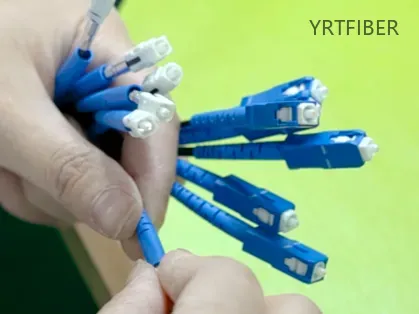
Frequently Asked Questions & Quick Inquiry
1×32 PLC Fiber Optic Splitter FAQ
Q1: What is a 1x32 PLC splitter used for?
A1: It is used to split a single optical signal into 32 separate paths, commonly used in FTTx, LAN, and telecom networks.
Q2: What connectors are available for the 1x32 PLC splitter?
A2: This splitter comes with SC connectors, available in UPC or APC polish.
Q3: What fiber type is supported by the 1x32 PLC splitter?
A3: It supports single-mode fibers, including G652D and G657A.
Q4: How does the mini module design benefit the installation?
A4: The mini module design provides space efficiency, ideal for high-density installations in telecom rooms or data centers.
Q5: What are the typical applications for this PLC splitter?
A5: It’s typically used for FTTx networks, LAN and telecom infrastructure, and optical signal distribution in high-density environments.
What is the difference between UPC and APC connectors in the 1x32 PLC fiber optic splitter?
UPC connectors have a flat - ended, highly polished ferrule, which provides low insertion loss and is suitable for general - purpose optical connections. APC connectors, on the other hand, have an angled ferrule (usually 8°). This angled design helps to reduce back - reflection, resulting in high return loss. APC connectors are often used in applications where minimizing signal reflections is critical, such as long - distance or high - performance optical links.
Can the 1x32 PLC fiber optic splitter be used with multimode fiber?
No, this splitter is specifically designed to be compatible with G652D and G657A single - mode fibers. Using it with multimode fiber may lead to poor signal performance as the optical characteristics of multimode and single - mode fibers are different. For multimode applications, a splitter designed for multimode fibers should be used.
Send Your Inquiry
Fill out the form below and we'll get back to you within 24 hours.


