

 Español
 Português
 لالعربية
 Русский
 Bahasa Indonesia
 Français
 Türkçe
 Bahasa Melayu

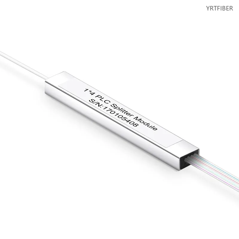
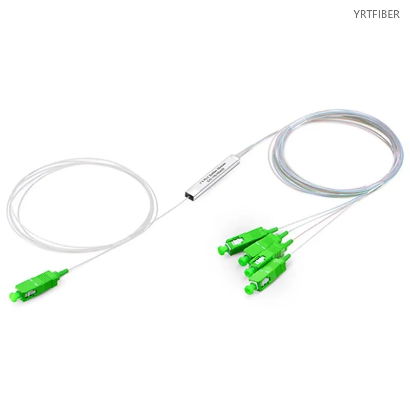
1x4 PLC Fiber Optic Splitter ,Mini Module Splitters– Single-mode G652D/G657A
1x4 configuration for splitting one optical signal into four paths.
Designed for **single-mode fiber** (G652D, G657A) for long-distance transmission.
Low insertion loss and high return loss for optimal signal quality.
Mini module design for space-efficient installation in high-density environments.
Available with SC, LC, FC, and ST connectors for easy integration.
What is a 1x4 PLC Fiber Optic Splitter?
A 1x4 PLC fiber optic splitter in a mini - module design is a device that splits a single optical signal into four paths, is compatible with single - mode fibers G652D and G657A for long - distance transmission, offers good signal performance, saves space, and has multiple connector options for network integration.
1x4 PLC fiber optic splitter Specification parameters
- Specification parameters
- OPTICAL CHARACTERISTICS
| Package Style | Mini Module |
| Configuration Type | 1×4 |
| Fiber Grade | G.657A1 |
| Fiber Mode | Singlemode |
| Connector Type | SC/APC |
| Split Ratio | Symmetrical |
| Input/Output Fiber Diameter | 900 μm |
| Input/Output Fiber Length | 1.5 m |
| Insertion Loss | ≤ 4.1 dB |
| Return Loss | ≥ 55 dB |
| Loss Uniformity | ≤ 0.4 dB |
| Directivity | ≥ 55 dB |
| Polarization Dependent Loss | ≤ 0.2 dB |
| Temperature Dependent Loss | ≤ 0.5 dB |
| Wavelength Dependent Loss | ≤ 0.3 dB |
| Operating Bandwidth | 1260 – 1650 nm |
| Steel Tube Dimensions (HxWxD) | 0.16″ × 1.97″ × 0.28″ (4×50×7 mm) |
| Temperature | Operating: –40 to 85 °C (–40 to 185 °F)Storage: –40 to 85 °C (–40 to 185 °F) |
Product Structure & Composition
Optical Splitting Core: Based on PLC technology, it evenly splits the incoming signal into four outputs, ensuring consistent signal integrity across all channels.
Mini‑module Housing: The compact housing protects the internal core from mechanical damage and dust, enabling easy installation in crowded enclosures.
Connectors: Available in SC, LC, FC, and ST types, they provide secure connections for single‑mode fibers G652D/G657A. LC suits high‑density cabling, while SC is widely used for its simplicity.

Benefits of 1x4 PLC fiber optic splitter
Precise Signal Splitting for Diverse Networks
The 1x4 configuration is well - suited for a variety of network scenarios. In FTTx networks, it can be used to distribute optical signals to a small group of end - users or to connect different network segments. In LANs, it helps in expanding the network connectivity to a limited number of devices, such as a small office setup. In data centers, it can be used for specific signal distribution tasks within a rack or a small - scale data center area.
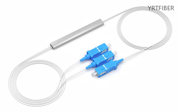
Excellent Signal Quality
With low insertion loss and high return loss, the splitter ensures that the optical signals are transmitted with minimal degradation. Low insertion loss means that the signal loses very little power as it passes through the splitter, while high return loss prevents signal reflections that could disrupt the overall signal quality. This results in stable and high - quality data transmission across the four split paths.
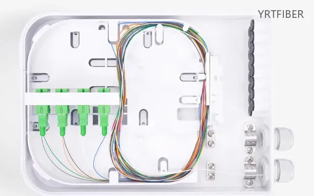
Space - efficient Installation
The mini - module design is a significant advantage in high - density network environments. It occupies less space in patch panels, optical distribution frames, or other network enclosures, allowing for more efficient use of available space. This enables the installation of multiple splitters in a limited area, facilitating neater cabling arrangements and better overall network management.

Easy Network Integration
The availability of multiple connector options (SC, LC, FC, and ST) makes it easy to integrate the splitter into existing network systems. Whether the network infrastructure is based on LC - equipped high - density switches, SC - connected patch panels, or FC/ST - terminated fiber optic cables, the 1x4 PLC fiber optic splitter can be easily connected without the need for additional adapters in most cases.
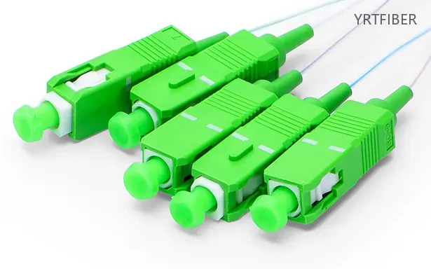
Engineering Applications 1x4 PLC fiber optic splitter
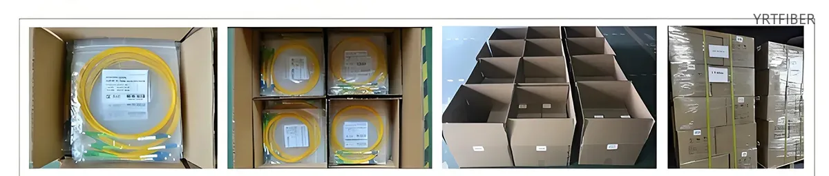
Shipping & Packaging

Product Comparison:
| Feature / Dimension | 1×8 PLC Splitter | 1×8 FBT Coupler | 1×4 PLC Splitter |
|---|---|---|---|
| Technology | Planar Lightwave Circuit (PLC) - semiconductor lithography, waveguide on silica substrate | Fused Biconical Taper (FBT) - traditional fusion of multiple fibers | Planar Lightwave Circuit (PLC) - same as 1×8 |
| Wavelength Range | 1260 - 1650 nm (full band) | 850 / 1310 / 1550 nm (single/dual/triple window only) | 1260 - 1650 nm (full band) |
| Split Ratio Options | Standard: 1×2, 1×4, 1×8, 1×16, 1×32, 1×64 | Customizable: 1×2, 1×3, 1×4, 1×8 (asymmetric ratios available) | Standard: 1×2, 1×4, 1×8, 1×16, 1×32, 1×64 |
| Split Uniformity | Excellent - evenly splits light across all outputs | Poor - uniformity degrades as split ratio increases | Excellent - same as 1×8 |
| Insertion Loss (typical) | ~9.8 dB (max), ≤10.5 dB | ~10.8 dB (worst arm) - cascaded from 7 × 1×2 couplers + 6 splices | ~7.2 dB (lower than 1×8) |
| Temperature Dependent Loss (TDL) | ±0.25 dB (-40 to 85°c) | ±0.45 dB (-5 to 75°c) - cascaded effect from 3 × 1×2 stages | ±0.25 dB (-40 to 85°c) |
| Device Size | Compact - suitable for high-density applications | Large and bulky for multi-channel splitters | Even more compact than 1×8 |
| Reliability / Failure Rate | High - single chip, low FIT | Lower - 7 discrete 1×2 couplers + 6 splices, multiplied failure risk | High - same as 1×8 |
| Relative Cost | Higher for small split ratios; lower per channel for high ratios | Lower for small ratios (1×2, 1×4); higher for 1×8 due to cascading | Lower than 1×8 PLC (fewer outputs) |
| Common Package Types | Bare fiber, ABS module, mini plug-in, fan-out, LGX cassette | Steel tube, ABS module | Same as 1×8 PLC |
| Typical Applications | PON (EPON/GPON), FTTH/FTTx, CATV, data communications, ODN | Smaller networks, short distances, custom asymmetric splits | Smaller PON splits, lower subscriber density, budget-sensitive projects |
1x4 PLC fiber optic splitter Selection Guide
When choosing between a 1x4 PLC fiber optic splitter and a 1x8 PLC fiber optic splitter, consider the scale and density of your network. If your network has low - to - medium - density requirements, such as a small - scale FTTx deployment serving a few end - users, a small - office LAN with a limited number of devices, or a specific area in a data center with a small number of connections, the 1x4 splitter is a good choice. Its lower insertion loss due to fewer split paths and more compact size can be beneficial in these scenarios.
However, if your network is of medium - density, like a medium - sized local network expansion, a smaller data center, or a telecom network segment serving a moderate number of users, the 1x8 splitter may be more appropriate. It offers a higher - density splitting solution to accommodate more connections.
Parameter - Best Fit
| Parameter | Best Fit |
|---|---|
| Low - to - medium - density network applications | 1x4 PLC Fiber Optic Splitter |
| Medium - density network applications | 1x8 PLC Fiber Optic Splitter |
| Small - scale FTTx deployments | 1x4 PLC Fiber Optic Splitter |
| Smaller data centers or medium - sized local network expansions | 1x8 PLC Fiber Optic Splitter |
Mixed deployment guidance:
In a large - scale network with a mix of high - density and low - density areas, a combination of 1x4 and 1x8 splitters can be used. 1x8 splitters can be installed in areas with a higher concentration of users or devices, such as the main distribution areas of a medium - sized data center. 1x4 splitters can be deployed in areas with a lower density of connections, like in smaller sub - networks or for connecting a limited number of devices in a specific area of an FTTx network. This approach optimizes cost - effectiveness and space utilization.
Installation Instructions of 1x4 PLC fiber optic splitter
Pre-installation Inspection: Visually inspect the splitter's housing and connectors for damage, cracks, or dirt. Make sure input/output port labels are clear and legible.
Connection: Select the appropriate connector type. Align and insert the fiber‑terminated connector (G652D/G657A) firmly into the input port. Repeat the same process for each of the four output ports, and label every connection clearly for future identification.
Mounting: Secure the splitter in a patch panel, distribution frame, or enclosure using the provided hardware. Ensure it is firmly fixed without straining the attached fibers.
Testing: Measure insertion loss at each output port with an optical power meter. If values exceed specifications, re‑check connections, clean connectors, and inspect for internal damage. Also verify that return loss meets the required standards.
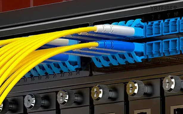
Download YRTFIBER Product Catalog
Factory Real Shot
Frequently Asked Questions & Quick Inquiry
1x4 PLC fiber optic splitter FAQ
Q1: What is the purpose of a 1x4 PLC splitter?
A1: The 1x4 PLC splitter is used to split a single optical signal into four paths, ideal for applications like FTTx, CATV, and LAN.
Q2: What fiber type does the 1x4 PLC splitter support?
A2: This splitter supports single-mode fiber (G652D, G657A) for long-distance transmission.
Q3: What is the advantage of the mini module design?
A3: The mini module design allows for space-efficient installation in high-density environments, such as data centers or telecom rooms.
Q4: What connectors are available for the 1x4 PLC splitter?
A4: It is available with SC, LC, FC, and ST connectors, compatible with UPC or APC polishing.
Q5: What is the insertion loss of this PLC splitter?
A5: The 1x4 PLC splitter features low insertion loss, ensuring excellent signal quality in high-density fiber networks.
Send Your Inquiry
Fill out the form below and we'll get back to you within 24 hours.


