

 Español
 Português
 لالعربية
 Русский
 Bahasa Indonesia
 Français
 Türkçe
 Bahasa Melayu

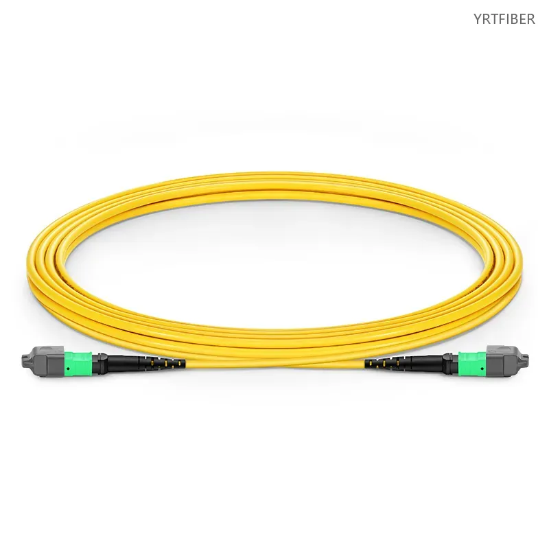
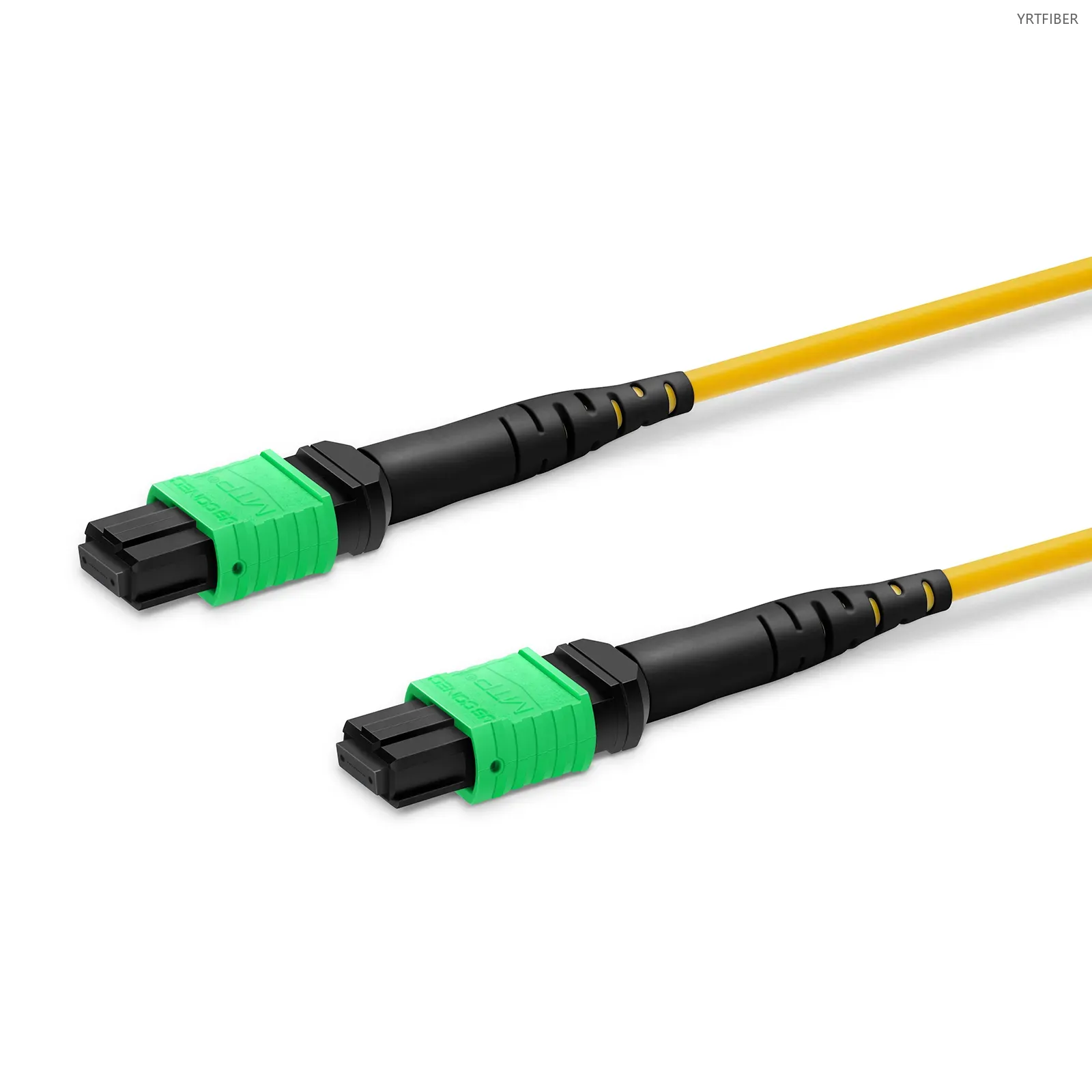
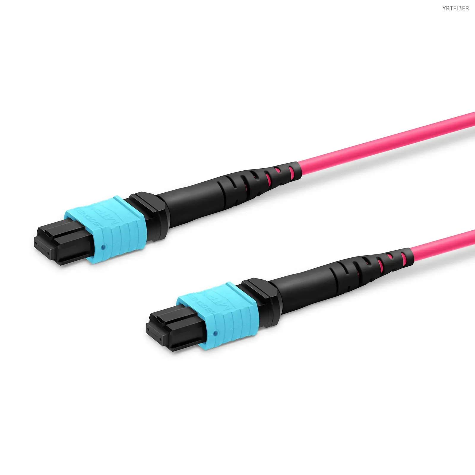
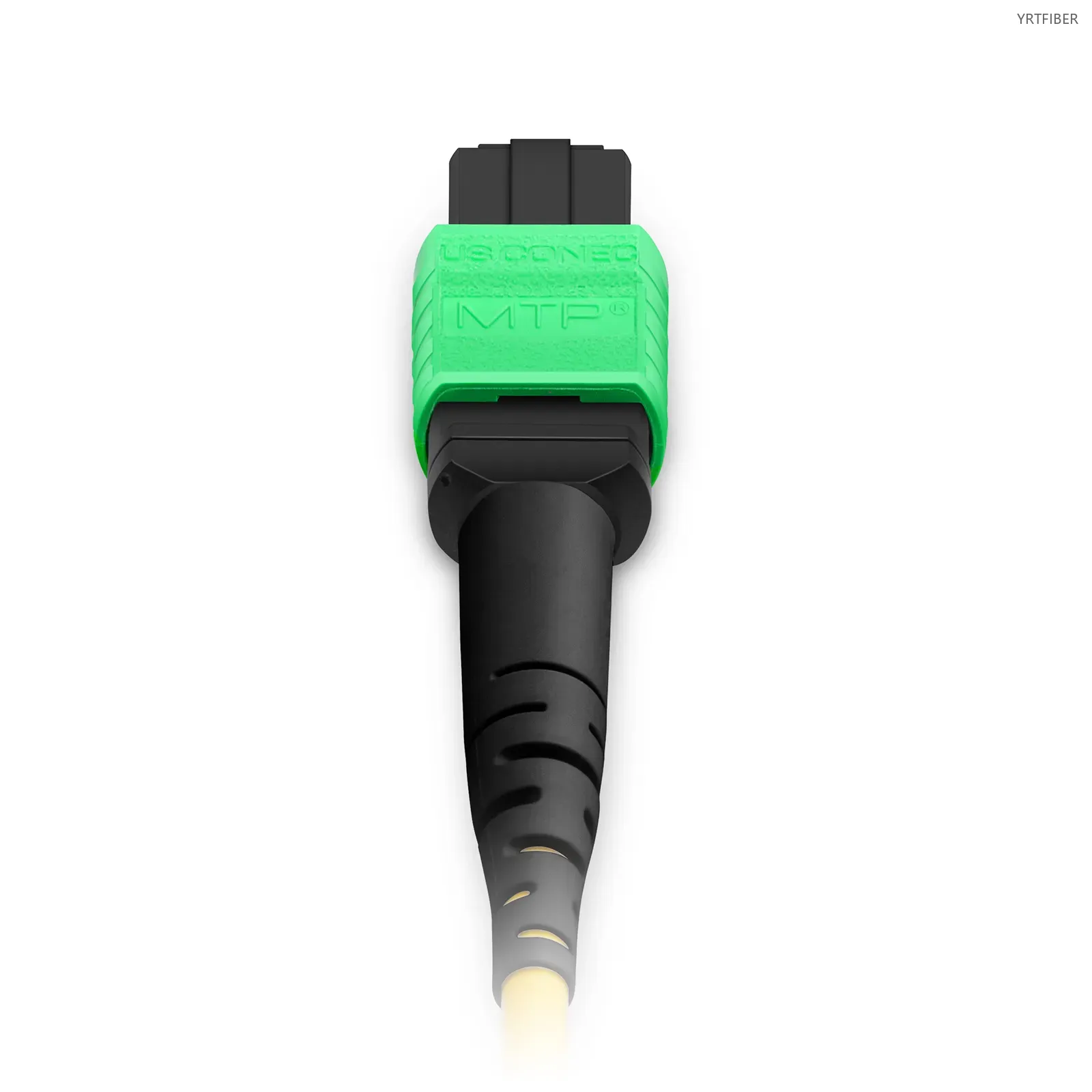
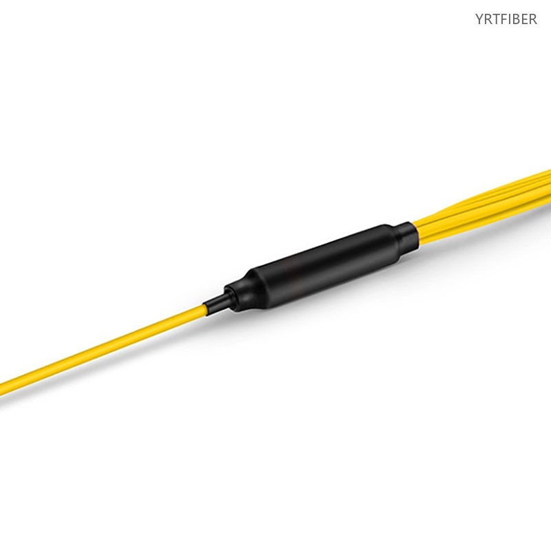
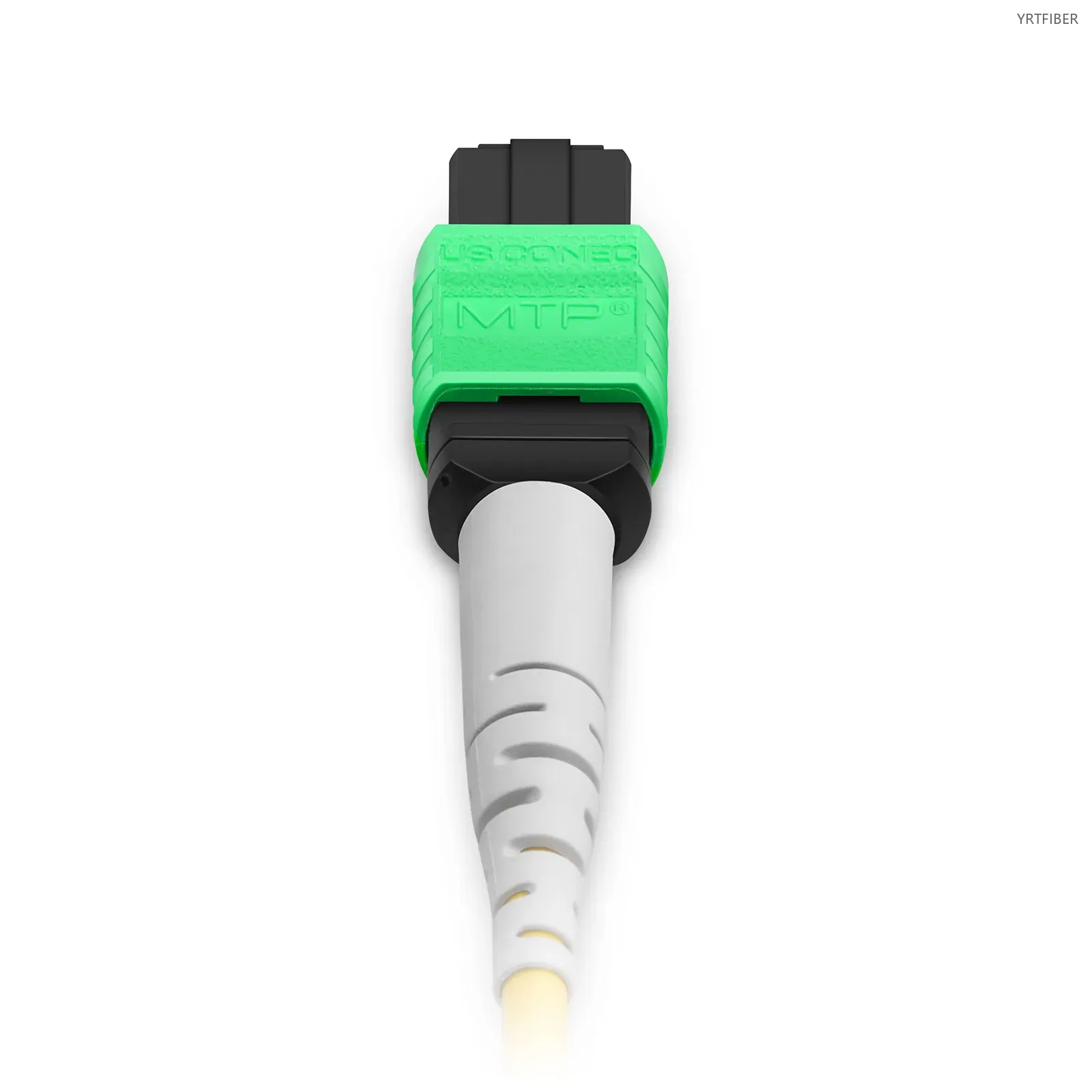
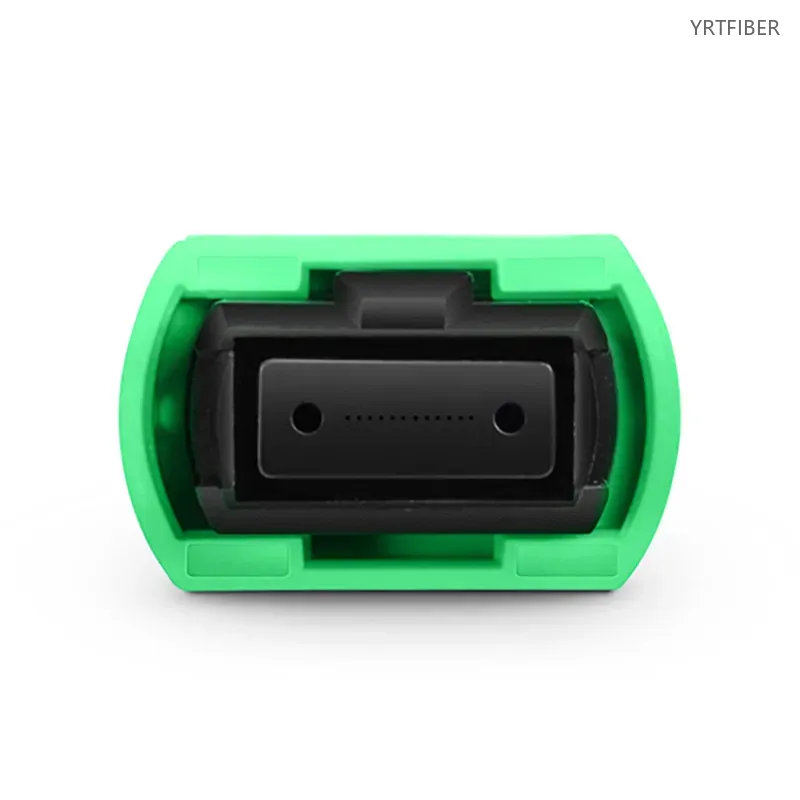
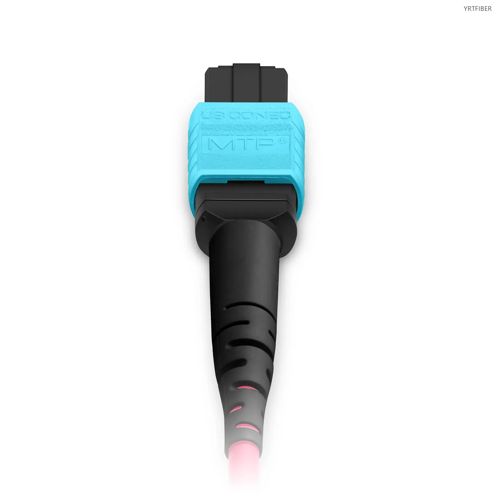
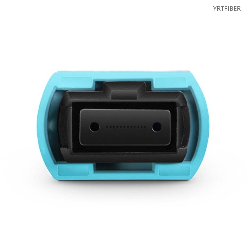
MTP to MTP High-Density Fiber Patch Cord – 8/12/24 Fibers, Multimode & Singlemode, OFNP
High‑density MTP patch cord for data center and telecom backbone interconnects.
Supports OM3/4/5 and G.652D/G.657.A for 40G/100G/400G links.
Features precision MTP connectors with low insertion/return loss.
Available in 8‑, 12‑, or 24‑fiber counts with polarities (A/B) and key positions.
Customizable lengths, jackets (OFNP), and plug‑and‑play for fast deployment in tight spaces.
What are MTP - MTP High - density Fiber Optic Patch Cords?
MTP - MTP high - density fiber optic patch cords are high - performance cables designed for high - density interconnections in data centers and telecom backbones. They come in multimode and singlemode versions, support high - speed data transmission up to 400G, use high - precision MTP connectors, and offer customizable features for seamless integration into network infrastructure.
MTP-MTP fiber optic patch cords Specification parameters
- Specification parameters
- OPTICAL CHARACTERISTICS
APC-APC Single Mode (OS2)
| Connector A | US Conec MTP® Elite Female (Pinless) | Connector B | US Conec MTP® Elite Female (Pinless) |
| Polish Type | APC to APC | Glass Fiber | Corning SMF-28® Ultra Fiber |
| Fiber Mode | OS2 9/125μm | Wavelength | 1310/1550nm |
| Fiber Count | 12 Fibers | Polarity | Type B |
| Cable Outside Diameter (OD) | 3.0mm | Cable Jacket | Plenum (OFNP) |
| Min. Bend Radius (optical fiber) | 10mm | Min. Bend Radius (Fiber Cable) | 10/5D (Dynamic/Static) |
| Connector Durability | 500 times | Tensile Strength | 80/240N (Long/Short Term) |
| Insertion Loss | 0.35dB Max (0.15dB Typ.) | Return Loss | ≥60dB |
| Attenuation at 1310nm | ≤0.32dB/km | Attenuation at 1550nm | ≤0.18dB/km |
| Operating Temperature | -10 to 70°C (14 to 158°F) | Storage Temperature | -40 to 85°C (-40 to 185°F) |
UPC-UPC Multimode (OM4)
| Connector A | US Conec MTP® Elite Female (Pinless) | Connector B | US Conec MTP® Elite Female (Pinless) |
| Polish Type | UPC to UPC | Glass Fiber | Corning ClearCurve® multimode fiber |
| Fiber Mode | OM4 50/125μm | Wavelength | 850/1300nm |
| Fiber Count | 12 Fibers | Polarity | Type B |
| Cable Outside Diameter (OD) | 3.0mm | Cable Jacket | Plenum (OFNP) |
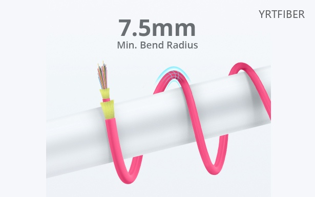
| Min. Bend Radius (Optical Fiber) | 7.5mm | Min. Bend Radius (Fiber Cable) | 20/10D (Dynamic/Static) |
| Connector Durability | 500 times | Tensile Strength | 80/240N (Long/Short Term) |
| Insertion Loss | 0.35dB Max (0.15dB Typ.) | Return Loss | ≥20dB |
| Attenuation at 850nm | ≤2.3dB/km | Attenuation at 1300nm | ≤0.6dB/km |
| Operating Temperature | -10 to 70°C (14 to 158°F) | Storage Temperature | -40 to 85°C (-40 to 185°F) |
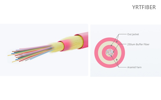
Product Structure & Composition
Fiber Core & Cladding
Multimode (OM3/4/5): 50/125μm. OM3: 10-40G short distance; OM4: 10-100G; OM5: 40-400G with SWDM.
Singlemode (G.652D, G657A): 9/125μm, for long distance/low loss, also short-reach low-dispersion use.
MTP Connector
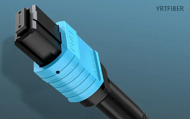
High-density multi-fiber connector (8/12/24 fibers). Uses precision alignment and supports polarities (A/B) and key positions for proper connection.
Outer Jacket
PVC: general indoor, cost-effective.
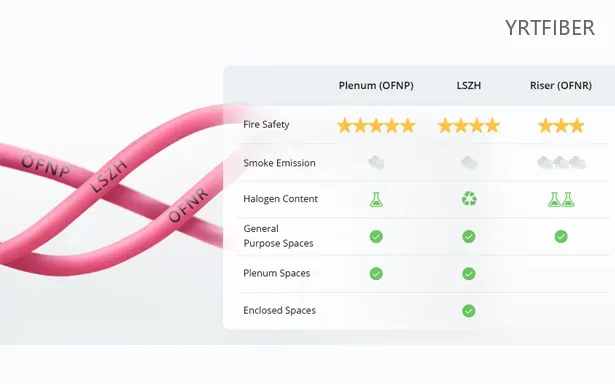
LSZH: low smoke, halogen-free, fire-safe.
OFNP: plenum-rated, strict fire codes.
Benefits of MTP-MTP fiber optic patch cords
High - speed Data Transmission
These patch cords support high - speed data transmission up to 400G, making them suitable for the latest high - bandwidth applications in data centers, such as 40G/100G/400G Ethernet. Whether it's for data center interconnects or telecommunications, they can meet the demand for rapid data transfer over short distances.
Excellent Optical Performance
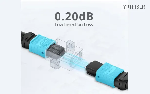
With low insertion loss and high return loss, MTP - MTP patch cords ensure better performance and signal integrity. This means that the optical signals can be transmitted with minimal degradation, resulting in reliable data transfer and smooth operation of high - speed networks.
Compatibility and Easy Integration
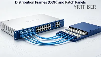
The patch cords are fully compatible with MTP/MPO systems, allowing for easy integration into existing network infrastructure. The support for various polarities (A/B) and key positions ensures that they can be connected correctly to other MTP/MPO - enabled equipment and patch panels without compatibility issues.
Customization Options
The availability of custom lengths and different jacket types (PVC, LSZH, OFNP) provides flexibility for various installation environments. This allows for higher port density, clearer routing, and fast plug - and - play deployment, especially in confined cabinet spaces. Customers can choose the length and jacket material that best suits their specific requirements.
Engineering Applications MTP-MTP fiber optic patch cords

Data Centers
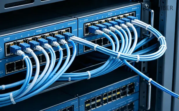
In data centers, MTP - MTP high - density fiber optic patch cords are used for high - density interconnections between servers, switches, and storage devices. Their ability to support high - speed data transmission up to 400G and high - density fiber management makes them ideal for enabling rapid data transfer and efficient use of space within the data center.

Telecom Backbones
Telecom backbones rely on these patch cords for short - reach, high - speed connections between different network nodes. The low insertion loss and high return loss ensure reliable signal transmission over short distances, while the high - density design helps in managing a large number of fibers in a compact space.
High - speed Ethernet Networks
For high - speed Ethernet networks operating at 40G/100G/400G, MTP - MTP patch cords provide the necessary connectivity. They can be used to connect network devices such as routers, switches, and access points, ensuring seamless high - speed data transfer within the network.
Shipping & Packaging
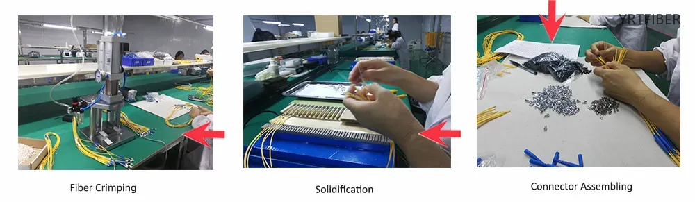
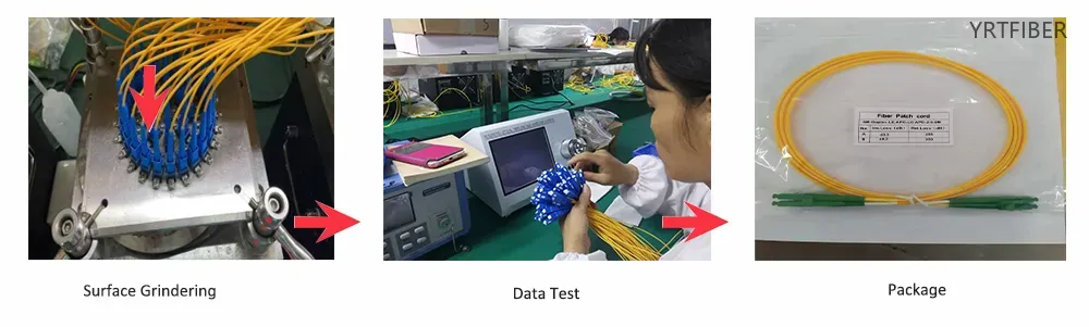
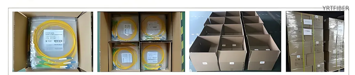

Product Comparison:
MTP-MTP vs LC Fiber Optic Patch Cord
| Comparison Dimensions | MTP-MTP High-Density Fiber Optic Patch Cord | Duplex LC Fiber Optic Patch Cord (Single/Multimode) |
|---|---|---|
| Connector Type and Interface | MTP (or MPO compatible) multi-core connectors, using MT ferrules (mechanical mating) and guide pins for precise alignment, with a push-pull locking design for insertion/removal. | |
| Fiber Core Count Density | Extremely High Density: One MTP connector can achieve the data capacity of 12 LC interfaces; within a 1U rack space, the MTP solution can accommodate 864 fibers, saving over 75% of cabling space compared to the same space. A single MTP patch cord can directly replace 12-24 LC/SC patch cords. | Low Density: Each LC patch cord manages only two fibers, and only about 144 cores (about 72 LC patch cords) can be placed in the same 1U space. This consumes a lot of space in the core switching area of large data centers and increases the difficulty of cabling management. |
| Structured and Polarity Configuration | Strict adherence to polarity management is required: The factory will preset the polarity A/B according to TIA/EIA standards. | |
| Advantages of Engineering Construction | (1) Plug and play deployment: All optical paths are 100% tested in the factory (loss, return loss, end face geometry, etc.), and one person can quickly complete the backbone fiber laying during construction; deploying a 144-core backbone only takes a few minutes, saving 1-2 hours compared to the LC solution; (2) Supports high parallel transmission: natively matches parallel transceivers such as QSFP, QSFP-DD and OSFP, directly supporting 40G SR4, 100G SR4/SR10 and even 400G/800G architecture; (3) The cable diameter is only 3.0 mm, and the bending radius can be as low as 7.5 mm, making it very easy to bend in high-altitude/compact spaces. | (1) Low technical threshold and strong versatility: It is compatible with almost all network devices and optical modules; (2) High cost flexibility: Finished cables can be purchased precisely according to actual distance requirements, and can be customized in extremely short distances of ≤30 m without the pressure of excessive investment; (3) Easier on-site fault handling: LC connectors are small in size and cleaning tools are widely available, allowing for quick replacement or repair of individual faulty jumpers; (4) Lower price per jumper. |
| Disadvantages of Engineering Construction | (1) Higher initial investment: The initial procurement cost of MTP/MPO components (module box, polarity conversion component, etc.) is higher than that of LC/SC solutions, which is a solution with a large one-time capital expenditure; (2) High requirements for on-site management and cleaning: Any contamination in the multi-core MT ferrule will affect the performance of the multi-fiber, and the maintenance and cleaning difficulty is far greater than that of the LC single-core solution. Special cleaning tools must be used; (3) Loss and polarity dependence: Link loss is more affected by the number of insertions and removals and dust control. The polarity must be strictly matched with the optical module and module box, otherwise the signal cannot be transmitted. | (1) When cabling in a large-scale high-speed data center, single-end device ports occupy a lot of physical space, resulting in crowded cabinets/patch panels and difficulty in airflow organization; (2) In scenarios with speeds of 40G and above, multiple LC patch cords are required to work with complex parallel transceivers, and the surge in the number of patch cords makes management and cabling extremely difficult; (3) When upgrading to higher bandwidth (such as 200G/400G) in the later stages, it is usually necessary to completely replace the cabling, and it is not possible to achieve a smooth upgrade like MTP. |
| Typical Engineering Applications | (1) Backbone interconnection of hyperscale data centers and cloud data centers (TOR to EOR, MDA-HDA-EDA area); (2) 40G/100G/400G parallel optical transmission (such as 40GBASE-SR4, 100GBASE-SR4/SR10, 400GBASE-SR16); (3) Scenarios using QSFP, QSFP-DD or OSFP optical modules; (4) High-density pre-terminated systems (such as MTP module boxes, high-density branch boxes). | (1) Enterprise-level traditional data centers, old system upgrades, and laboratory racks; (2) Low-speed (1G/10G) or low-density cabling links; (3) Point-to-point long-distance single-mode connections (OS2 with LR/LR4 optical modules); (4) Campus network access equipment with small scale and low density requirements; (5) Static scenarios with short distances between devices and insensitivity to cabling speed and redundancy requirements. |
| Typical Insertion Loss (IL) for Single-Mode Transmission | Elite/Ultra-Low Insertion Loss (Low Loss) IL ≤ 0.35 dB, Standard ≤ 0.75 dB; Return Loss (RL) ≤ 60 dB (APC polishing). Factory end-face testing includes IL, RL, and 100% end-face geometry testing. | LC APC single-mode connection IL ± 0.35 dB (Elite/Premium) or ± 0.50 dB (Standard); return loss ± 55 dB (UPC) or ± 65 dB (APC). Generally, factories only perform random sampling, not 100% inspection. |
| Typical IL for multimode transmission (OM3/OM4) | Elite IL ± 0.35 dB, Standard IL ± 0.50 dB, supports SR4 standard distance in 40G links: OM3 ± 100 m, OM4 ± 150 m. | High-quality LC has an IL of ±0.25–0.35 dB (OM3/OM4); standard grade IL is ±0.50–0.70 dB. 10G transmission distance: OM3 ±300 m, OM4 ±550 m, not directly related to parallel optics. |
MTP-MTP fiber optic patch cords Selection Guide
When choosing between MTP - MTP and LC - LC fiber optic patch cords, consider your network requirements. If your application is in a high - density environment such as a data center or telecom backbone, and you need to support high - speed data transmission up to 400G, MTP - MTP patch cords are the better choice. Their high - density fiber configuration, support for high - speeds, and compatibility with MTP/MPO systems make them suitable for these demanding scenarios.
On the other hand, if your network has less - crowded cabling requirements and the speed needs are generally up to 100G or lower, LC - LC patch cords can be more appropriate. They offer simplicity and are well - suited for general - purpose fiber - optic connections.
Parameter - Best Fit
| Parameter | Best Fit |
|---|---|
| High - density environments with high - speed (400G) requirements | MTP - MTP |
| General - purpose connections with speeds up to 100G or lower | LC - LC |
| Space - saving in data centers and telecom backbones | MTP - MTP |
| Single - fiber or duplex connections in less - crowded environments | LC - LC |
Mixed deployment guidance:
In a network with a mix of high - density and general - purpose areas, MTP - MTP patch cords can be used in high - density, high - speed sections such as server - to - switch connections in data centers. LC - LC patch cords can be deployed in areas with lower - density requirements, like connecting individual user devices to the network. This approach allows for an optimized network design that balances performance and cost - effectiveness.
Installation of MTP-MTP high-density fiber optic patch cords
Pre‑inspection - Check jacket for cuts/kinks. Ensure MTP connectors are clean, alignment keys and latches intact, fibers properly terminated.
Cleaning - Wipe ferrule end‑face with isopropyl alcohol on lint‑free swab (parallel to fiber axes). Dry with clean swab.
Connection - Align key & polarity with port/adapter. Insert gently and lock securely. Use tool if needed for high‑density setups.
Cable routing - Maintain bend radius (≈10× cable diameter for multimode). Use ties/trays; avoid bending or twisting that could cause signal loss.
Post‑test - Measure insertion/return loss with power meter or network analyzer. Clean again or replace if values exceed specs.
Download YRTFIBER Product Catalog
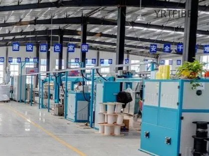
Factory Real Shot
Intelligent Manufacturing Foundation: Class 10.000 Cleanroom and Fully Automated Production Lines
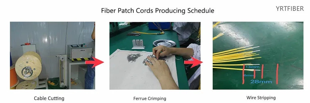
The facility boasts a 60.000 ㎡; cleanroom equipped with 21 automated single-core and MPO patch cord production lines. Core equipment includes high-precision fiber optic cleavers (tolerance±0.08 mm), FLC automatic termination machines, and UV curing systems. Daily output reaches thousands of connectors, with industry-leading quality consistency.
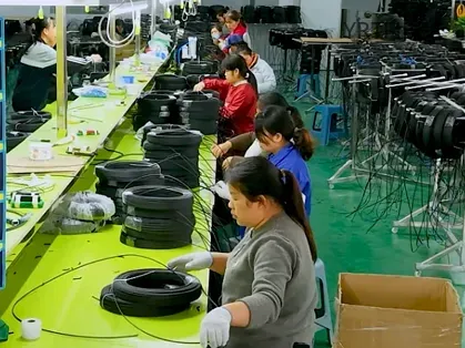
2. Precision Manufacturing Process: From Micron-Level Cutting to High-Speed Polishing
End face angle tolerance ±0.5°, six-axis fusion splicing core deviation ≤1 Mm. Supports multi-layer sheaths (LSZH / PVC / OFNP), automated polishing achieves PC / UPC / APC surface types. Single-shift (11-hour) capacity reaches up to 7.000 connectors.
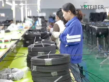
3. Closed-Loop Quality Control: 100% Inspection + Environmental Verification
Each jumper cable undergoes 400x interference end-face inspection, automatic contamination identification, and OTDR insertion loss testing. Randomly sampled samples also undergo environmental tests including temperature, humidity, and tensile stress, fully complying with IEC/TIA standards.
Frequently Asked Questions & Quick Inquiry
MTP-MTP fiber optic patch cords FAQ
Q1: What is an MTP to MTP fiber patch cord used for?
A1: MTP to MTP fiber patch cords are used for connecting high-density fiber optic systems, especially in 40G/100G/400G Ethernet networks, data centers, and telecom environments.
Q2: What fiber types are available for MTP to MTP patch cords?
A2: These patch cords are available in both multimode (OM3. OM4. OM5) and singlemode (G652D, G657A) fibers.
Q3: What is the maximum speed supported by these patch cords?
A3: These patch cords support data transmission speeds up to 400G for short-range fiber-optic connections.
Q4: What connector types do MTP to MTP patch cords use?
A4: These patch cords use MTP/MPO connectors with 8-core, 12-core, or 24-core configurations, compatible with high-density fiber systems.
Q5: Can I customize the length and jacket material of the patch cords?
A5: Yes, we offer custom lengths and jacket materials (PVC, LSZH, OFNP) to meet specific installation and environmental requirements.
What is the main advantage of MTP - MTP patch cords over other types?
The main advantage is their high - density design, which enables efficient fiber management and space optimization in high - density environments. They also support extremely high - speed data transmission up to 400G, making them suitable for the latest high - bandwidth applications in data centers and telecom backbones.
Can MTP - MTP patch cords be used in a multimode network?
Yes, MTP - MTP patch cords are available in multimode versions (OM3. OM4. OM5), making them suitable for multimode networks. Each multimode fiber type is optimized for different levels of high - speed data transmission, allowing for flexibility in choosing the right fiber for the specific network requirements.
How do I ensure proper connection of MTP - MTP patch cords?
MTP - MTP patch cords support different polarities (A/B) and key positions. When connecting, make sure to align the polarities and key positions correctly with the corresponding MTP/MPO equipment or patch panels. This will ensure a proper connection and prevent issues such as incorrect signal routing or poor optical performance.
Send Your Inquiry
Fill out the form below and we'll get back to you within 24 hours.


