

 Español
 Português
 لالعربية
 Русский
 Bahasa Indonesia
 Français
 Türkçe
 Bahasa Melayu

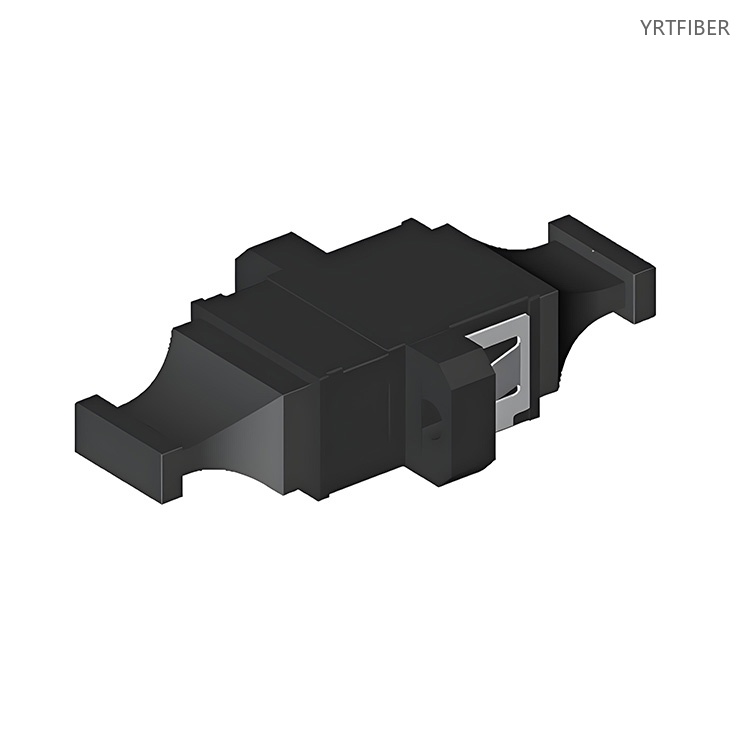
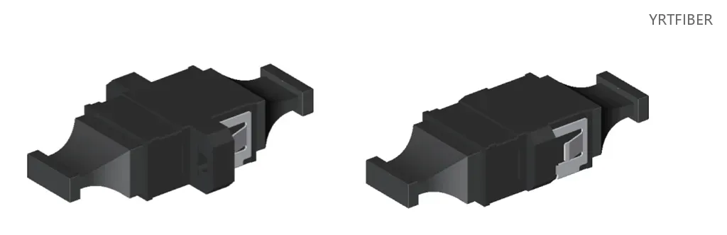
High‑Density MPO Fiber Optic Adapter for Data Center & High‑Speed Network Connectivity
MPO interface supporting 8 to 48 fiber configurations (12. 24. 32. 48 options).
Precision guide pins ensure accurate ferrule alignment and low insertion loss.
Compatible with both single‑mode and multimode fiber systems.
High‑durability zirconia or metal alignment sleeve, rated for 500 to 1.000 mating cycles.
Compact footprint enables high‑density panel mounting (up to 72 fibers per 1U).
Flange or snap‑in mounting options for easy installation on patch panels and enclosures.
Suitable for high‑speed parallel transmission (40G to 400G) and backbone cabling.
Flame‑retardant plastic or metal housing for indoor and controlled environments.
What is an MPO Fiber Optic Adapter?
The MPO fiber optic adapter is a high‑density coupling device that aligns and connects two MPO connectors, each housing multiple optical fibers (typically 12, 24, or 48) within a single ferrule. By consolidating many fibers into one interface, it dramatically increases port density, simplifies cabling, and enables high‑speed parallel transmission-making it essential for modern data centers, cloud infrastructures, and 400G/800G network upgrades.
MPO Fiber Optic Adapter Specification parameters
- Specification parameters
- OPTICAL CHARACTERISTICS
| 1 | Insertion Loss (dB) | dB | ≤0.2 dB |
| 2 | Repetitiveness (dB) | dB | ≤0.1 dB |
| 3 | Interchangeability (dB) | dB | ≤0.2 dB |
| 4 | Plug Times | Times | 200 times |
| 5 | Tensile Strength | G | 200–600 G |
| 6 | Operating Temperature | Celsius | -40 ~ +85 ℃ |
| 7 | Storage Temperature | Celsius | -40 ~ +110 ℃ |
| 8 | Humidity | Celsius | 95% RH (Non-Packaging) |
| Ref. | Dimensional Tolerance | |
|---|---|---|
| Min | Max | |
| S | 3.4 | 3.6 |
| N | 2.4 | 2.6 |
| O | 5.0 | 5.1 |
| P | 5.7 | 5.9 |
| R | 7.8 | 8.2 |
| H | 12.6 | 13.0 |
Product Structure & Composition
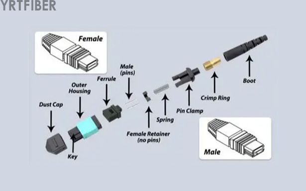
MPO‑to‑MPO interface; each connector has a multi‑fiber ferrule (e.g., 12‑fiber row), with guide pins in the adapter for precise fiber alignment.
Ceramic or metal split sleeve holds ferrules; guide pins (male) mate with pin holes (female) to prevent rotational misalignment.
Key (alignment rib) on the housing ensures correct polarity mapping (transmit‑receive orientation) for parallel and duplex systems.
Flame‑retardant plastic or metal housing with integrated flange for screw or snap‑in mounting to patch panels and enclosures.
Benefits of MPO Fiber Optic Adapter
High‑Density Fiber Consolidation
An MPO adapter combines up to 48 fibers in a single connector, slashing the space required for cabling. In a 1U rack panel, you can achieve over 72 fibers (6×12‑fiber MPO ports), compared to only 24-48 LC duplex ports. This density boost is critical for scaling data center capacity without expanding floor space.

Precision Alignment for Low Loss
The combination of guide pins and precision alignment sleeves ensures that all fiber cores are simultaneously aligned with micron accuracy. Typical insertion loss is ≤0.2 dB for single‑mode and ≤0.1 dB for multimode, enabling error‑free transmission over long links and high‑speed parallel optics (40G/100G/400G).
Rapid Deployment and Simplified Cabling
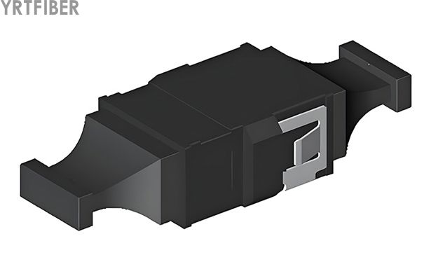
By using MPO pre‑terminated trunk cables, you can deploy hundreds of fibers in minutes—far faster than field‑terminating individual connectors. The adapter's snap‑in mounting further accelerates installation, reducing network rollout time and labor costs significantly.
Flexible Polarity and Keying Options
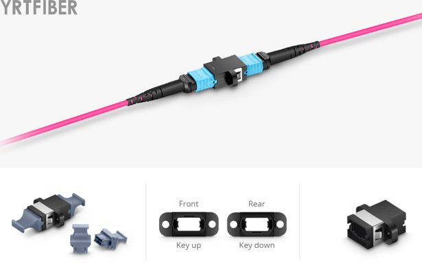
MPO adapters support standard polarity schemes (Type A, B, C) through key orientation. This flexibility allows seamless integration with different transceiver and panel designs, ensuring that transmit‑receive pairs are correctly aligned without complex re‑termination.

Engineering Applications MPO Fiber Optic Adapter

yperscale Data Centers
MPO adapters are the backbone of hyperscale cloud and AI data centers, where thousands of fibers connect leaf‑spine architectures. They support 40G/100G/400G Ethernet breakout and spine‑to‑leaf links, handling massive east‑west traffic with minimal latency.

Parallel Optics and High‑Speed Transceivers
QSFP/QSFP‑DD and OSFP transceivers use MPO interfaces for 40G‑800G parallel lanes. The adapter directly couples these transceivers to MPO trunk cables, enabling high‑bandwidth aggregation in switch‑to‑server and inter‑rack connections.
Backbone and Distribution Cabling
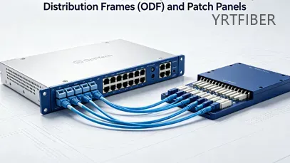
In main distribution frames (MDF) and intermediate distribution frames (IDF), MPO adapters terminate high‑fiber‑count backbone cables. They facilitate structured cabling for floor‑to‑floor and building‑to‑building links, simplifying migration to higher speeds.

FTTX and Central Office Consolidation
Telecom central offices use MPO adapters to aggregate feeder fibers from OLTs to distribution panels, reducing patch field complexity and enabling rapid service turn‑up for FTTH/FTTx networks.
Shipping & Packaging

Product Comparison:
MPO Adapter (12‑fiber) vs. LC Duplex Adapter
| Feature / Dimension | MPO Adapter (12‑fiber) | LC Duplex Adapter |
|---|---|---|
| Structure / Form Factor | Single port housing 12 fibers (or more). Rectangular body with guide pins. Keyed for polarity. Flange/snap‑in mount. | Duplex LC port (2 fibers). Compact push‑pull housing. Color‑coded (blue/aqua). Flange/snap‑in mount. |
| Port Density (per 1U panel) | Up to 6 MPO ports = 72 fibers (using 12‑fiber). With 24‑fiber, up to 144 fibers. | Typically 24 to 48 duplex ports = 48 to 96 fibers. |
| Coupling Mechanism | Push‑pull with guide pins. Requires proper key orientation. Latching via side clips. | Push‑pull latch (RJ‑45 style). Tool‑less, intuitive. |
| Typical Applications | High‑density backbone, parallel optics (40G‑400G), hyperscale data centers. | Server‑to‑switch patching, low‑density interconnects, legacy systems. |
| Key Engineering Pros | - Extremely high fiber density saves space. - Pre‑terminated trunks reduce field labor. - Supports parallel multi‑lane signals. | - Simpler handling and cleaning. - Individual fiber management easier. - Widely compatible with legacy equipment. |
| Key Engineering Cons | - More complex polarity planning. - Cleaning and inspection of multi‑fiber ferrule requires specialized tools. - Higher initial cost for trunks. | - Lower density, requires more panels. - Slower deployment for many fibers. |
| Tolerance to Vibration / Shock | Good, but guide pins can be damaged if mishandled. | Good, but push‑pull latch can loosen under extreme vibration. |
| Housing Material Options | UL94‑V0 plastic or metal. Available with or without flange. | UL94‑V0 plastic or metal, full/reduced flange. |
| Fiber Mode Options | Single‑mode (green) and multimode (beige/aqua for OM3/OM4). | Single‑mode (blue) and multimode (beige/aqua). |
| Cost (Relative) | Higher per port for adapter, but lower total system cost for high‑fiber counts. | Lower per port, but higher panel and cable management costs for dense systems. |
| Maintenance & Handling | Requires MPO‑specific cleaning tools (cassettes, end‑face inspection probes). Polarity tracking is critical. | Standard cleaning swabs; easier individual fiber tracing. |
MPO Fiber Optic Adapter Selection Guide
How to Choose the Right MPO Fiber Optic Adapter
Selecting an MPO adapter involves several key decisions. First, determine the fiber count: common options are 12. 24. and 48 fibers. 12‑fiber is most prevalent for 40G/100G; 24‑fiber is used for 400G (SR8/DR4) applications; 48‑fiber supports ultra‑high‑density trunks.
Second, choose fiber type: single‑mode (G652D/G657A) for long‑distance and high‑speed (100G‑400G) over longer reaches; multimode (OM3/OM4/OM5) for short‑range data center links (up to 100m–300m). Color‑coded housings are green for SM, beige/aqua for MM.
Third, decide on polarity: Type A (straight), Type B (reversed pair), or Type C (crossed pairs). The adapter's key orientation (key up vs. key down) must match your polarity scheme and mating connectors to ensure correct TX‑RX pairing.
Fourth, consider mounting: flange (with screws) for secure panel installation, or snap‑in for quick tool‑less mounting. For environments with frequent re‑patching, snap‑in is preferred.
Finally, evaluate environment: standard plastic housings are fine for indoor data centers; metal housings offer better thermal and mechanical stability for industrial or outdoor cabinets.
Installation Instructions
Panel Mounting
For snap‑in adapters, align with cutout and push to engage clips; for screw‑mount, insert and secure with screws. Ensure key orientation matches polarity before locking.
Connecting MPO Cables
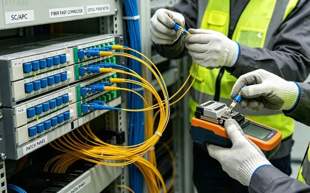
Inspect MPO end‑faces with microscope; clean if needed. Align key with slot, insert straight until firm click. For pin‑side, ensure male pins mate with female holes.
Cable Management and Polarity Verification
Route MPO trunks with min bend radius of 10× diameter (>30 mm for SM). Secure with ties or trays. After install, verify polarity using light source/power meter or MPO tester to confirm TX‑RX alignment.
Download YRTFIBER Product Catalog
Factory Real Shot
Frequently Asked Questions & Quick Inquiry
MPO Fiber Optic Adapter FAQ
What fiber counts are supported by your MPO adapters?
We offer MPO adapters with configurations typically ranging from 8 to 48 fibers, and can support higher densities upon request to meet large-scale deployment needs.
Are your MPO adapters compatible with different fiber types?
Yes, our adapters are compatible with both single‑mode and multi‑mode fibers and can be customized for specific transmission standards like 40G, 100G, and beyond.
Can I get OEM or customized packaging for MPO adapters?
Absolutely. We welcome OEM and ODM requests, including customized packaging, labeling, and design tailored to your brand requirements.
Do you provide sample units for evaluation?
Free samples are available under certain conditions. Freight costs may apply. Please contact our sales team for details.
What warranty coverage do you offer?
We provide a two‑year warranty. Products with quality issues are eligible for free return within three months, and one year of maintenance support is included.
What is the typical insertion loss of an MPO adapter?
Typical insertion loss is ≤0.2 dB for single‑mode and ≤0.1 dB for multimode, depending on the ferrule quality and connector polish.
How many fibers can an MPO adapter support?
MPO adapters are available for 8, 12, 16, 24, 32, and 48 fibers. The most common are 12‑fiber and 24‑fiber configurations.
Can I use an MPO adapter for both single‑mode and multimode?
Yes, but you must select the correct version for the fiber type, as the ferrule hole sizes and alignment tolerances differ. Always use color‑coded housings to avoid mismatches.
What is the keying/polarity importance?
Key orientation (up/down) determines how the fibers are paired across the adapter. This is critical for maintaining transmit‑receive polarity in duplex and parallel systems. Type A, B, and C polarity schemes require specific key alignments.
How do I clean an MPO adapter?
Use a dry cleaning cassette or reel‑based cleaner designed for MPO/MTP adapters. Insert the cleaner into the adapter port and follow the tool's instructions. For end‑face inspection, use an MPO‑compatible microscope with a 2.5mm or 1.25mm ferrule adapter.
What is the mating cycle rating?
Most MPO adapters are rated for 500 to 1,000 mating cycles with minimal loss increase (≤0.1 dB).
Can MPO adapters be used for 400G Ethernet?
Yes. 400G SR8 uses a 16‑fiber MPO (or two 12‑fiber) connector; 400G DR4/FR4 often use 12‑fiber MPO with breakout. Ensure the adapter supports the specific fiber count and polarity required.
Are MPO adapters field‑installable?
Adapters themselves are passive and require no field assembly. However, MPO connectors on cables can be field‑terminated with specialized tools, though pre‑terminated trunks are recommended for best performance.
What is the difference between MPO and MTP?
MTP is a registered trademark of US Conec, referring to a high‑performance version of the MPO connector with improved mechanical specifications. Most MTP connectors are interoperable with standard MPO adapters, but check compatibility for precision applications.
Can I use a 12‑fiber adapter with a 24‑fiber connector?
No. The ferrule size and pin arrangements differ. You must match the adapter to the connector's fiber count.
Send Your Inquiry
Fill out the form below and we'll get back to you within 24 hours.


