

 Español
 Português
 لالعربية
 Русский
 Bahasa Indonesia
 Français
 Türkçe
 Bahasa Melayu
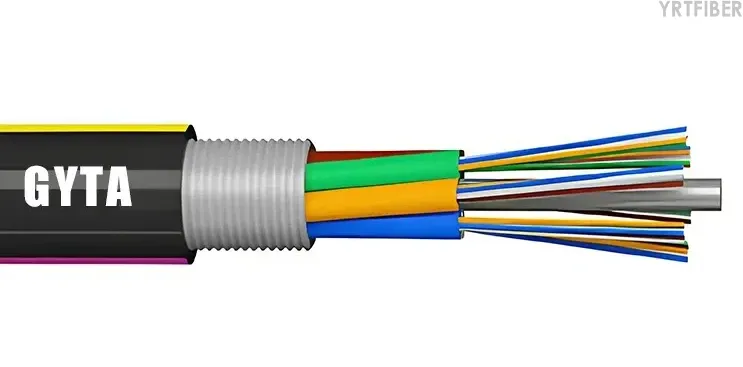
A stranded fiber optic cable is an optical cable in which several loose tubes, fillers, or optical units are helically or SZ-stranded around a central strength member. This construction is widely used in outdoor backbone, duct, aerial, and selected direct-buried networks because it gives the cable controlled fiber excess length, mechanical stability, water-blocking space, and flexible fiber-count design. This article explains the structure, how stranding works, common cable types, suitable applications, testing requirements, and selection points. The term should not be confused with copper conductor stranding or with simply counting each optical fiber as a "strand."
What Is a Stranded Fiber Optic Cable?
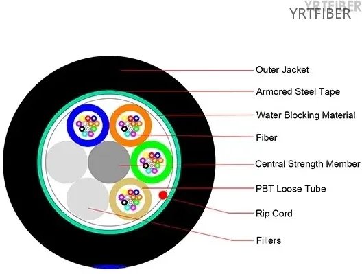
A stranded fiber optic cable is a cable structure where fiber-containing units are arranged around a central strength member instead of placing all fibers in one central tube. In most outdoor telecom cables, the fiber-containing units are PBT loose tubes. Each tube contains colored optical fibers and tube filling gel or dry water-blocking elements. The loose tubes are then stranded around a central steel wire, FRP rod, or other strength member.
The most common form is the stranded loose tube fiber optic cable. It is used when the network needs higher fiber counts, better mechanical balance, and more flexible cable design than a simple central loose tube cable can provide.
Important distinction:
Optical fiber manufacturing produces the glass fiber itself.
Fiber optic cable manufacturing converts finished optical fibers into protected cable structures.
Stranding is one cable-manufacturing step that arranges loose tubes, fillers, and strength elements into a stable cable core.
Why Stranding Is Used in Outdoor Fiber Cable
Stranding helps the cable control mechanical stress during pulling, bending, temperature change, and long-term service. In a stranded loose tube design, the fibers are not fixed tightly along the cable axis. The loose tube and stranding geometry provide fiber excess length, so the optical fibers can tolerate limited cable elongation without immediately taking the full tensile load.
Stranding also makes it easier to build different fiber counts. A cable can use several active loose tubes, several filler rods, or a mix of both. This gives manufacturers a consistent cable core geometry across different fiber counts while keeping tube positions, cable roundness, and sheath extrusion more stable.
In many outdoor cable families, stranding also leaves space for water-blocking yarn, water-blocking tape, filling compound, ripcords, armor, and sheath layers. These components are selected according to the installation environment, not only according to fiber count.
Main Structural Components
The exact design depends on the product model and project specification, but a typical stranded loose tube fiber optic cable includes the following components.
| Component | Common material or design | Function | Important limitation |
|---|---|---|---|
| Optical fiber | Single-mode fibers such as ITU-T G.652.D, G.655, or G.657; multimode fibers when specified | Carries the optical signal | Fiber category and attenuation must be stated by wavelength and standard; do not assume one value for all fibers |
| Loose tube | Usually PBT or another qualified polymer | Protects fibers and provides space for fiber excess length | Tube material alone does not define the whole cable performance |
| Tube filling or dry blocking | Filling gel, water-blocking yarn, or water-blocking powder/tape system | Limits water migration inside or around the tube | "Water-blocking" does not mean the cable is suitable for long-term underwater use |
| Central strength member | Steel wire, FRP, or other specified strength member | Provides tensile support and core stability | Metallic and non-metallic members have different grounding, weight, and electrical behavior |
| Loose tube stranding layer | Helical or SZ stranded tubes and fillers | Builds a balanced cable core and controls mechanical behavior | Stranding pitch and excess fiber length are design-specific and should not be guessed from the model name |
| Water-blocking layer | Water-blocking tape, yarn, filling compound, or combined system | Reduces longitudinal water penetration | Test method and pass/fail condition must be specified |
| Armor layer, if used | Steel tape, aluminum tape, corrugated steel tape, or non-metallic reinforcement | Improves crush, rodent, or impact protection | armor cable is not automatically suitable for every direct burial condition |
| Outer sheath | PE for many outdoor cables; LSZH or flame-retardant materials where specified | Environmental, mechanical, and handling protection | Outdoor PE sheath is not the same as indoor flame-retardant or fire-resistant sheath |
How Stranded Fiber Optic Cable Is Manufactured
Step 1: Finished optical fibers are inspected and colored
Cable manufacturing starts with finished optical fibers, not with glass preform drawing. Incoming fibers are checked according to the required fiber type, coating condition, attenuation requirement, and identification plan. Fibers are then colored so technicians can identify each fiber during splicing and termination.
Step 2: Fibers are placed into loose tubes
Colored fibers are placed into loose tubes. In many outdoor stranded cables, the tube is extruded from PBT because it provides mechanical protection and dimensional stability for the optical fibers. The tube may be filled with gel or designed with dry water-blocking materials depending on the cable specification.
Step 3: Loose tubes and fillers are stranded around a central strength member
The loose tubes are stranded around a central strength member. When the cable uses SZ stranding, the stranding direction periodically reverses. This allows easier mid-span access and helps control cable handling during manufacturing and installation. In conventional helical stranding, the tubes follow one continuous direction.
The stranding process must control tube tension, lay length, cable core diameter, and fiber excess length. These values affect mechanical behavior, but they are design parameters rather than universal public values.
Step 4: Water-blocking materials are applied
Outdoor stranded fiber optic cable normally requires water-blocking protection. The design may use water-blocking yarn, water-blocking tape, filling compound, or a hybrid system. The correct method depends on whether the cable is for duct, aerial, buried, or transition routes.
Water-blocking performance should be verified by an applicable IEC 60794 water penetration method or project-specified equivalent. A product description should state the test condition, sample length, water head, duration, and acceptance criterion rather than using only the word "waterproof."
Step 5: Armor, strength yarn, or sheath layers are added
After the cable core is formed, the manufacturer adds the required protection layers. GYTA-type cables commonly use an aluminum-polyethylene moisture barrier. GYTS-type cables commonly use steel tape armor. GYFTY-type cables use non-metallic strength elements where all-dielectric routing is required. Double-sheath and armored structures such as GYTA53 or GYFTY53 are selected for higher mechanical risk or duct-to-buried transition sections.
Model names are useful, but the datasheet and cross-section should always be checked. Different manufacturers and national naming systems may not use exactly the same construction rules.
Step 6: The finished cable is tested and packed
Finished stranded fiber optic cable should be tested before shipment. Typical checks include fiber attenuation, cable diameter, sheath appearance, printing, tensile performance, crush resistance, bend performance, water penetration, and temperature cycling where required. The cable is then wound on drums with direction marking, length marking, model identification, and shipping protection.
Stranded Loose Tube Cable vs Central Tube Cable
| Comparison point | Stranded loose tube fiber optic cable | Central loose tube fiber optic cable |
|---|---|---|
| Basic structure | Several loose tubes or fillers stranded around a central strength member | One central tube contains the fibers |
| Typical fiber count range | Suitable for medium and high fiber counts; exact range depends on design | Common for lower fiber counts and compact access cables |
| Cable diameter | Usually larger than a comparable central tube cable | Usually compact |
| Mechanical balance | Good core balance when tubes and fillers are properly designed | Simple structure but less flexible for high-count designs |
| Mid-span access | SZ stranded designs can support practical mid-span access when designed for it | Access depends on tube design and installation method |
| Typical applications | Outdoor duct, backbone, access, aerial, and some buried routes | Shorter access routes, distribution links, drop transition, or compact outdoor cable |
| Main limitation | More complex manufacturing and larger cable size | Limited scalability for high fiber count and route-specific mechanical requirements |
Common Types of Stranded Fiber Optic Cable
| Cable type | Typical construction | Typical use | Main limitation |
|---|---|---|---|
| GYTA stranded fiber optic cable | Stranded loose tube core with aluminum-polyethylene moisture barrier and PE sheath | Outdoor duct, conduit, telecom access, and backbone routes | Aluminum tape is a moisture barrier/light armor, not equivalent to steel tape armor |
| GYTS stranded fiber optic cable | Stranded loose tube core with steel tape armor and PE sheath | Duct, outdoor access, backbone, and routes needing stronger crush or rodent protection | Metallic armor may require grounding and corrosion consideration |
| GYFTY stranded fiber optic cable | Stranded loose tube all-dielectric cable with FRP strength member and non-metallic reinforcement | Duct routes, power environments, lightning-prone areas, and routes avoiding metallic elements | All-dielectric does not automatically mean high tensile span capability |
| GYTA53 stranded armored cable | Stranded loose tube cable with inner sheath, steel tape armor, and outer PE sheath | Direct buried, duct-to-buried transition, and higher-risk underground routes | Direct burial suitability still depends on soil, trench, load, and project standard |
| GYFTY53 or non-metallic reinforced buried cable | FRP central strength member, reinforced sheath, and armor or non-metallic protection according to the exact specification | Buried or duct routes where tensile strength, moisture protection, or electrical isolation requirements must be checked carefully | A cable with steel tape armor is not all-dielectric even if its central strength member is FRP |
| Figure-8 stranded loose tube cable | Stranded or loose-tube cable core with an integrated messenger wire | Aerial outdoor access and distribution routes | Span, sag, wind, ice, and pole hardware must be engineered; do not select only by fiber count |
Suitable Applications
Stranded fiber optic cable is suitable when the project needs a balanced outdoor cable core, medium or high fiber count, water-blocking design, and mechanical protection options.
Typical suitable applications include:
Outdoor telecom backbone routes
Metro fiber and access networks
Underground duct and conduit systems
FTTH/FTTx feeder and distribution sections
Campus backbone and industrial park networks
Aerial routes when the cable is specifically designed as self-supporting or figure-8
Duct-to-buried transition sections when the cable has suitable armor and sheath layers
Applications That Require Another Cable Design
Stranded construction is useful, but it does not solve every installation problem.
Cases requiring another design or additional engineering include:
Indoor riser or plenum routes that need specific flame-retardant or fire-safety ratings
Long-span aerial routes that require ADSS, figure-8, or other span-rated cable design
Direct burial in rocky soil, high-load road crossings, or rodent-heavy routes without confirmed armor and crush test data
Long-term underwater, lake, river, or sewer installation without a cable family designed and tested for that environment
High-voltage power corridors where metallic elements create grounding, induction, or lightning concerns; use a verified all-dielectric design when electrical isolation is required
Microduct blowing routes where cable diameter, friction, stiffness, and blowing test performance are more important than conventional stranding
Testing Requirements and Applicable Standards
No single tensile load, crush load, bend radius, or attenuation value should be generalized across all stranded fiber optic cables. Test results must be tied to the cable model, fiber type, test method, wavelength, load condition, duration, and allowable attenuation change.
| Test or check | Purpose | Applicable standard or method reference | Result conditions to state |
|---|---|---|---|
| Optical attenuation | Confirms fiber transmission performance after cabling | ITU-T G.652, G.655, G.657 for fiber category; IEC 60793 and IEC 60794 references where applicable | Wavelength, fiber type, cable length, measurement method, maximum attenuation |
| Tensile performance | Checks cable behavior under installation or operating tension | IEC 60794-1-101:2024, or IEC 60794-1-21 where still specified by the project | Short-term or long-term load, duration, residual attenuation change, sheath/core damage acceptance |
| Crush resistance | Evaluates resistance to lateral compression | IEC 60794-1-103 where applicable, or IEC 60794-1-21 Method E3 in legacy specifications | Plate shape, load, load length, duration, attenuation change, physical damage |
| Impact resistance | Evaluates response to repeated or specified impact | IEC 60794-1-104:2024, or project-specified equivalent | Impact energy, number of impacts, impact position, attenuation change |
| Bend performance | Confirms cable performance under specified bending | IEC 60794-1-111:2023 Bend, Method E11 | Mandrel diameter, number of turns, test temperature if specified, attenuation change |
| Torsion performance | Checks behavior when the cable is twisted | IEC 60794-1-107:2025 Torsion, Method E7 | Sample length, angle, number of cycles, attenuation change, sheath damage |
| Temperature cycling | Verifies optical stability under temperature change | IEC 60794-1-201:2024 Temperature cycling, Method F1 | Temperature range, cycle count, dwell time, attenuation change |
| Water penetration | Checks longitudinal water-blocking performance | IEC 60794-1-2 guidance and applicable IEC 60794 water penetration method, or project-specified F5 method | Sample length, water head, duration, leakage criterion |
| Sheath and marking inspection | Confirms cable identification and manufacturing quality | Product specification, IEC 60794 family, customer purchase specification | Diameter, sheath thickness, print content, meter marking, drum length |
Selection Checklist
Define the installation route: duct, direct buried, aerial, indoor-outdoor transition, or mixed route.
Confirm fiber type: G.652.D, G.655, G.657, multimode, or another specified fiber.
Confirm fiber count and tube plan: number of fibers per tube, active tubes, fillers, and color code.
Select central strength member: steel wire for metallic strength or FRP for all-dielectric routing.
Select water-blocking method: gel-filled, dry water-blocking, or hybrid design.
Select armor only when the route needs it: aluminum tape, steel tape, corrugated steel tape, steel wire, or non-metallic reinforcement.
Confirm sheath material: PE for many outdoor routes, LSZH or flame-retardant sheath only when the installation environment requires it.
Check bending radius, pulling tension, drum length, cable diameter, and installation equipment limits.
Request test reports that match the exact cable structure and fiber count, not only a similar product family.
Verify grounding and corrosion requirements when the cable includes metallic armor, metallic strength members, or messenger wires.
Common Mistakes to Avoid
Do not describe a stranded fiber optic cable as if the glass fibers are twisted like copper conductors.
Do not use "stranded cable" and "armored cable" as the same term. A stranded cable may be armored or non-armored.
Do not assume GYTS, GYTA, GYFTY, and GYTA53 have the same mechanical rating.
Do not claim a cable is direct-buried only because it has steel tape armor.
Do not list steel tape or steel wire as jacket material. They are armor or strength elements, not the outer sheath.
Do not give one bend radius or tensile load for all stranded fiber optic cables.
Do not state a lifetime such as 25 or 30 years without a verified project specification, material qualification, or reliability basis.
Frequently Asked Questions
Is a stranded fiber optic cable the same as a stranded copper cable?
No. In a stranded copper cable, the conductive copper wires may be physically stranded to carry electrical current. In a stranded fiber optic cable, the term usually means that loose tubes or optical units are stranded around a central strength member. The optical fibers transmit light and are protected inside the cable structure; they are not used as metallic conductors.
Is every stranded fiber optic cable armored?
No. Stranded describes the cable core arrangement. Armor describes a protective layer such as steel tape, aluminum tape, corrugated steel tape, steel wire, or non-metallic reinforcement. GYFTY is commonly a stranded non-metallic outdoor cable, while GYTS is commonly a stranded steel tape armored cable.
Why are loose tubes used in stranded outdoor cable?
Loose tubes protect optical fibers and provide controlled space for fiber excess length. This helps reduce direct fiber stress when the cable is pulled, bent, or exposed to temperature changes. The tube also provides space for gel or dry water-blocking materials where required.
What is SZ stranding in fiber optic cable?
SZ stranding is a stranding method in which the tube direction periodically reverses along the cable length. It is widely used in loose tube cable manufacturing because it supports controlled cable core geometry and can make mid-span access easier when the cable is designed for that purpose.
Is stranded fiber optic cable suitable for direct burial?
Only if the exact cable design is rated for the burial environment. Direct burial may require stronger armor, double sheath, water-blocking performance, crush resistance, rodent protection, and soil-specific installation protection. A standard stranded outdoor duct cable should not be treated as a Direct Burial Cable without checking its datasheet and test report.
Which is better, stranded loose tube or central loose tube cable?
Neither structure is universally better. Stranded loose tube cable is usually preferred for higher fiber counts, outdoor backbone routes, and designs needing flexible tube and armor combinations. Central loose tube cable is often more compact and suitable for lower fiber counts or short access links. The right choice depends on route type, fiber count, pulling condition, bend control, and mechanical risk.
Does metallic armor need grounding?
Metallic armor, steel strength members, and messenger wires may require bonding and grounding according to local electrical codes, operator standards, and site conditions. This is especially important near power lines, substations, lightning-prone routes, and industrial facilities.
Conclusion
Stranded fiber optic cable is best understood as a cable-core construction, not a generic synonym for any multi-fiber cable. In a typical stranded loose tube design, several fiber-containing tubes are stranded around a central strength member, then protected with water-blocking materials, optional armor, and an outer sheath. This structure is widely used for outdoor duct, backbone, access, aerial, and selected buried routes because it supports flexible fiber counts and controlled mechanical performance.
The correct cable should be selected by route condition, fiber type, fiber count, strength member, water-blocking method, armor requirement, sheath material, and verified test data. For engineering documents and product pages, performance values should always be reported with the applicable IEC or ITU-T reference, test condition, unit, and acceptance criterion.
Recommended Internal Links
GYTS stranded loose tube Armored Fiber Optic Cable
GYTA aluminum tape duct fiber optic cable
GYTA53 outdoor fiber optic cable
Duct fiber optic cable selection
Direct buried fiber optic cable selection
Armored optical cable construction
References
IEC 60794-1-1:2023, Optical fibre cables - Part 1-1: Generic specification - General. https://webstore.iec.ch/en/publication/68873
IEC 60794-1-2:2021, Optical fibre cables - Part 1-2: Generic specification - Basic optical cable test procedures - General guidance. https://webstore.iec.ch/en/publication/64652
IEC 60794-3:2022, Optical fibre cables - Part 3: Outdoor cables - Sectional specification. https://webstore.iec.ch/en/publication/67229
IEC 60794-1-101:2024, Mechanical test methods - Tensile, Method E1. https://webstore.iec.ch/en/publication/82653
IEC 60794-1-104:2024, Mechanical test methods - Impact performance. https://webstore.iec.ch/en/publication/82734
IEC 60794-1-107:2025, Mechanical test methods - Torsion, Method E7. https://webstore.iec.ch/en/publication/90796
IEC 60794-1-111:2023, Mechanical test methods - Bend, Method E11. https://webstore.iec.ch/en/publication/77493
IEC 60794-1-201:2024, Environmental test methods - Temperature cycling, Method F1. https://webstore.iec.ch/en/publication/78499
ITU-T G.652 (08/2024), Characteristics of a single-mode optical fibre and cable.
https://www.itu.int/rec/T-REC-G.652
ITU-T G.655 (11/2009), Characteristics of a non-zero dispersion-shifted single-mode optical fibre and cable.
ITU-T G.657 (08/2024), Characteristics of a bending-loss insensitive single-mode optical fibre and cable.


