Español
 Português
 لالعربية
 Русский
 Bahasa Indonesia
 Français
 Türkçe
 Bahasa Melayu


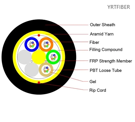
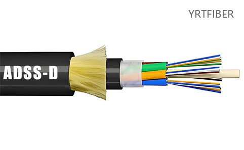
ADSS-S Single Jacket All-Dielectric Self-Supporting Aerial Fiber Optic Cable
- Product ModelADSS-S
- Fiber Core Count2-288 Cores
- Outer JacketPE/AT
- StandardDL/T 788-2004 & IEC60794-1
what is adss-s fiber optic cable
ADSS-S fiber optic cable is an all-dielectric self-supporting single-jacket aerial cable built with loose-tube stranded fibers and aramid yarn strength members under a PE (or anti-track) outer sheath, enabling long-span, power-free installation directly on overhead power transmission lines.
ADSS-S Fiber Optic Cable Specification parameters
- Specification parameters
- OPTICAL CHARACTERISTICS
Technical parameters
| Out Diameter (mm) | Reference weight (kg/km) | Daily max working tension (KN) | Max working tension (KN) | Break Strength (KN) | Strength Member CSA (mm²) | Modulus of Elasticity (kN/mm²) | Heat Expansion Coefficient (×10⁻⁸/K) | Suitable Span (m) | ||||
|---|---|---|---|---|---|---|---|---|---|---|---|---|
| PE sheath | AT sheath | A | B | C | D | |||||||
| 12.5 | 125 | 136 | 1.5 | 4 | 10 | 4.6 | 7.6 | 1.8 | 160 | 100 | 140 | 100 |
| 13.0 | 132 | 142 | 2.25 | 6 | 15 | 7.6 | 8.3 | 1.5 | 230 | 150 | 200 | 150 |
| 13.3 | 137 | 148 | 3 | 8 | 20 | 10.35 | 9.45 | 1.3 | 300 | 200 | 290 | 200 |
| 13.6 | 145 | 156 | 3.6 | 10 | 24 | 13.8 | 10.8 | 1.2 | 370 | 250 | 350 | 250 |
| 13.8 | 147 | 159 | 4.5 | 12 | 30 | 14.3 | 11.8 | 1.0 | 420 | 280 | 400 | 280 |
| 14.5 | 164 | 177 | 5.4 | 15 | 36 | 18.4 | 13.6 | 0.9 | 480 | 320 | 460 | 320 |
| 14.9 | — | — | — | — | — | — | — | — | 570 | 380 | 550 | 380 |
| 15.1 | 179 | 193 | 7.95 | 22 | 53 | 26.4 | 18 | 0.3 | 670 | 460 | 650 | 460 |
| 15.5 | — | — | — | — | — | — | — | — | 750 | 530 | 750 | 510 |
| 15.6 | 194 | 208 | 10.5 | 28 | 70 | 33 | 19.6 | 0.1 | 800 | 560 | 800 | 560 |
| 16.3 | — | — | — | — | — | — | — | — | 880 | 650 | 880 | 650 |
| 16.8 | — | — | — | — | — | — | — | — | 1000 | 750 | 1000 | 760 |
| 17.2 | — | — | — | — | — | — | — | — | 1100 | 800 | 1100 | 830 |
| 17.9 | — | — | — | — | — | — | — | — | 1180 | 880 | 1180 | 900 |
Zone A: 25 m/s wind, 0 mm ice · Zone B: 35 m/s, 0 mm · Zone C: 10 m/s, 5 mm ice, 2.5 N/m · Zone D: 10 m/s, 10 mm ice, 4.4 N/m.
Span values assume no height difference and 1% installation sag. Fibre count 2–288, grouped in loose tubes of up to 12 (288 cores = 24 tubes); the OD follows the span and load zone, so one diameter step covers a range of core counts and the tube/core assignment is confirmed on the order drawing. “—” = mechanical value supplied with the order drawing.
Optical properties
| G.652 | G.655 | 50/125μm | 62.5/125μm | |
|---|---|---|---|---|
| attenuation (+20℃) | ≤3.0dB/km @850nm | ≤3.0dB/km @850nm | ||
| ≤1.0dB/km @1300nm | ≤1.0dB/km @1300nm | |||
| ≤0.36dB/km @1310nm | -- | |||
| ≤0.22dB/km @1550nm | ≤0.23dB/km @1550nm | |||
| bandwidth (Class A) | ≥500MHZ·km @850 | ≥500MHZ·km @850 | ||
| ≥1000MHZ·km @1300 | ≥600MHZ·km @1300 | |||
| Numerical aperture | 0.200±0.015NA | 0.275±0.015NA | ||
| cutoff wavelength | ≤1260nm | ≤1480nm |
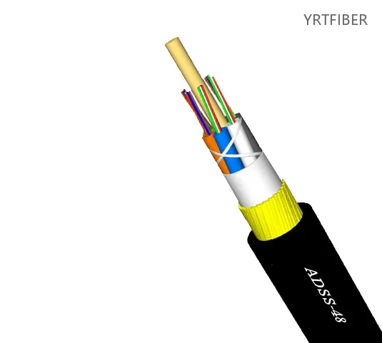
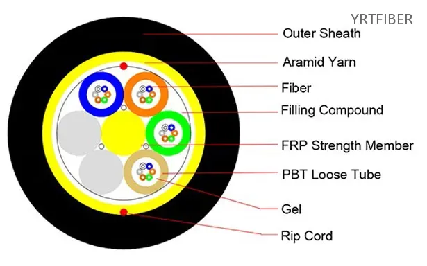
Product Structure & Composition
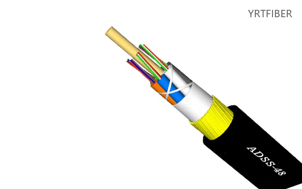
Complete cable structure (from outside to inside):
Outer Sheath - Protects the entire cable from environmental and mechanical stresses.
Aramid Yarn - Provides tensile strength and acts as a rodent deterrent.
Rip Cord - Allows easy removal of the outer sheath without tools.
FRP Strength Member - Fiber Reinforced Plastic rod that offers rigidity and anti-buckling strength.
PBT Loose Tube - Polybutylene terephthalate tube that houses the optical fibers loosely.
Gel - Water‑blocking gel that prevents moisture ingress inside the loose tube.
Fiber - The optical glass fiber that transmits light signals.
Filling Compound - Additional filler (often a thixotropic compound) that surrounds the fiber and blocks water.
Benefits of ADSS-S Fiber Optic Cable
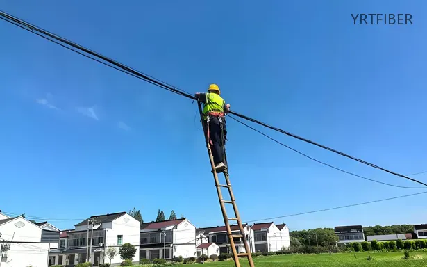
Extra‑long span capability
Span is set by cable OD and load zone, not by a single headline number: our standard table covers 160–1180 m across Ø12.5–17.9 mm, with 800 m at Ø15.6 mm in Zone A/C (no height difference, 1% installation sag).
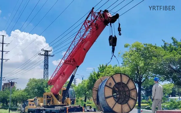
Power‑free installation
No electrical power required during deployment.
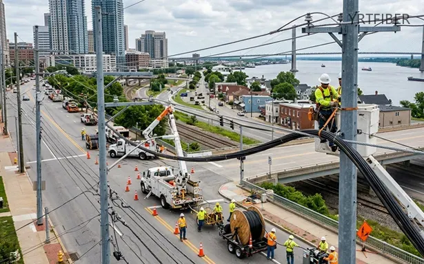
Lightweight & small diameter
Reduces load on cable towers and struts caused by freezing and wind.
High durability
Tensile strength and temperature resistance, with a service life of 30 years or more.
Engineering Applications ADSS-S Fiber Optic Cable
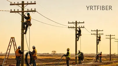
Rural Broadband and FTTH Feeder Routes
ADSS-S connects access nodes and distribution points on pole routes. Match the cable to pole spacing and wind and ice loads. Use drop cable for the final connection to the building. For duct, direct burial or indoor sections, select cable made for that installation.
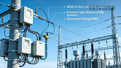
Utility Communication Networks
ADSS-S connects communication nodes along power lines. Check the mounting position and electric field before choosing PE or AT sheath. Non-metallic construction alone does not confirm suitability for a power-line route.
Selection guide: PE Sheath vs AT Sheath in ADSS Cable: Which One Should You Choose?.
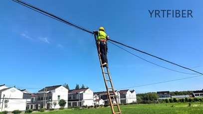
Valley and River Crossings
ADSS-S can be used for valley and river crossings when the cable design meets the span and load requirements. Check sag, tension, clearances and fittings. If the route exceeds the cable limits, choose another cable design or route.
Selection guide: Picking ADSS Cable? Start with Span, Not Fiber Count..
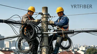
Existing Overhead Route Upgrades
ADSS-S adds fiber capacity along existing pole and tower routes. Check support capacity, mounting points, clearances and fittings. Agree on the installation method and any outage with the route owner.
Product Comparison:
ADSS-S (Single Sheath ADSS) VS ADSS-DS (Double Sheath ADSS) VS Figure-8 (Figure-8 Self-Supporting) VS OPGW (Optical Ground Wire)
| Feature / Dimension | ADSS-S | ADSS-DS | Figure-8 (Self-Supporting) | OPGW |
|---|---|---|---|---|
| Laying Distance (Max. span) | 160–420 m (Ø12.5–13.8 mm); 100–280 m in zone D | 480–1180 m (Ø14.5–17.9 mm); 320–900 m in zone D | 100-500 m (but >300 m may cause excessive sag) | Up to 1000 m+ (very long crossing spans) |
| Structural Features | Single PE/AT (Anti-Tracking) outer sheath; aramid yarn as primary strength member; loose tube gel-filled/filled-free design; all-dielectric (non-metallic). | Double sheath (inner + outer PE/AT); double layer of aramid yarn for enhanced tensile strength; all-dielectric construction with additional mechanical protection. | “8” shaped cross-section with integrated steel messenger wire; metallic core; optical fibers housed separately from supporting steel strand. | Steel/aluminum tube containing optical fibers stranded with Al-clad steel and/or aluminum alloy wires; dual-function: grounding + communication. |
| Typical Applications | Medium voltage (≤110 kV) power lines; short to medium spans (sized by cable OD and load zone); urban/rural distribution networks; FTTH backbone in mild environments. | High voltage (≥110 kV) power lines; long spans (sized by cable OD and load zone); harsh weather regions (rivers, valleys, heavy wind/ice zones); highways crossing. | Short span aerial deployment (<500 m); telecom/general purpose; rural broadband; budget‑sensitive projects with mild climate; no high‑voltage interference. | Extra-high voltage (220 kV+) transmission lines; new construction or ground wire replacement; backbone power grid; areas requiring high lightning/shield performance. |
| Pros in Engineering | Lightweight, low wind/ice load; easy one-step installation; no grounding required; for medium voltage; corrosion immunity; AT jacket available for tracking resistance. | Mechanical strength for long spans; enhanced UV/weather resistance; dual sheath for extra durability; minimal electrical tracking risk; dielectric protection. | Simple and fast installation (no separate messenger); low initial cost; widely available hardware; integrated steel strand eliminates extra supporting wire. | Dual functionality (grounding + communication); high tensile strength (up to 150 kN+); lightning/short-circuit withstand; long span capability (>500 m). |
| Cons in Engineering | Limited span (<150 m); PE jacket unsuitable for HV lines (>110 kV); requires careful sag/tension design; AT jacket adds cost for higher voltage use. | Heavier and larger diameter; higher upfront cost; more complex installation planning; requires precise hardware matching; higher material consumption. | Cannot be used near HV lines due to metallic messenger (EMI/electrical hazards); steel strand prone to corrosion; heavier weight per km (~300 kg/km); shorter lifespan (~15 yrs). | Metallic structure requires proper grounding; higher initial investment; complex installation (must match line design); difficult for retrofitting existing lines without ground wire replacement. |
| Cost (Relative) | Lowest among ADSS family. e.g., 24‑core for 100m span ~$0.25‑0.35/m; AT jacket adds 15‑25%. | Higher than ADSS-S. Additional aramid + outer jacket increase material cost; long‑span design (500m) 24‑core up to $0.90‑1.20/m. | Low initial cost (about 0.8‑1.2 USD/m for common spec), but higher long‑term TCO (maintenance and earlier replacement). | Highest. For 24‑core, market price typically $0.70‑1.40/m; specialized engineering increases overall project budget significantly. |
| Maintenance Difficulty | Low. No corrosion/rust; periodic visual inspection; regular cleaning needed in polluted areas; quick damage repair; minimal specialized tools. | Low to Medium. Extra sheath reduces environmental wear; internal inspection harder; more aramid means more complex re‑tensioning; otherwise similar to ADSS-S. | Medium. Steel strand needs rust protection and grounding checks; higher repair complexity; potential messenger separation issues; sag monitoring required. | Medium. Requires periodic ground resistance/continuity testing; harder to access fiber core; specialized joint hardware and trained personnel needed. |
| Span Capability (typical) | 160–420 m (Ø12.5–13.8 mm); 100–280 m in zone D | 480–1180 m (Ø14.5–17.9 mm); 320–900 m in zone D | 100 m-500 m, but >300 m may cause excessive sag; integrated steel strand. | Up to 1000 m+; for long crossing spans (rivers, canyons). |
| Voltage Compatibility | ≤110 kV (PE jacket); AT jacket extends to higher voltages (≥110 kV) but single sheath limits extreme HV use. | ≥110 kV, suitable for up to 220 kV+; widely used in EHV lines; double jacket reduces electrical tracking. | Not recommended near power lines (>1 kV); metallic components cause safety hazards and EMI. | ≥220 kV; standard for UHV/EHV; integrated as shield wire. |
| Lifespan / Durability | 25+ years (AT jacket extends life in HV environment). | 30+ years; double sheath adds abrasion/UV protection. | ~15 years (steel corrosion and fatigue). | 30+ years (metallic parts require corrosion care). |
| Environmental Suitability | Coastal, mild, industrial (with AT jacket); standard UV protection; good for medium wind/ice. | Extreme weather, high UV, heavy ice/wind zones, high salinity; for challenging terrains. | Mild climates, low corrosion risk; not suitable for coastal or high‑humidity areas without coating. | Any terrain, but needs proper grounding; lightning/short-circuit performance. |
ADSS-S Fiber Optic Cable Selection Guide
ADSS-S Fiber optic cable Installation (Short Version)
1. Plan & Inspect: Survey route, check voltage level (≤110kV for PE sheath; ≥110kV needs AT sheath). Inspect cable reels and hardware. Perform OTDR pre-test.
2. Hardware Mounting: Install suspension clamps 1–2m below phase conductors. Use proper sheaves (min. 12"diameter). Add vibration dampers for spans >100m.
3. Stringing: Place reel on stand with brake. Pull via pulling grip and swivel, tension ≤20% of RBS. Maintain communication between operators.
4. Sag & Clamp: Adjust sag using laser (follow sag‑tension table). Install permanent suspension/dead‑end hardware.
5. Finalize: Waterproof splice points. Perform OTDR acceptance test (≤0.25 dB/km @1550nm). Keep bending radius ≥30× cable OD during pull, ≥10× after.
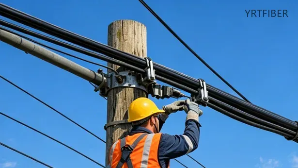
Download YRTFIBER Product Catalog
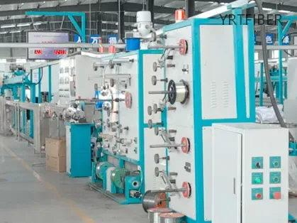
Factory Real Shot
Complete optical cable production line
We have a complete optical cable production line with an annual output of over 100.000 kilometers of optical cable.
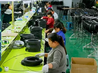
Skilled workers
The factory has a team of skilled workers, and this stable workforce ensures our product quality and delivery capabilities.
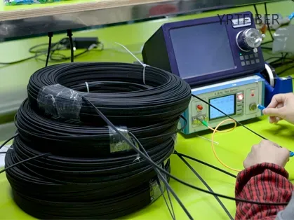
Quality Control Laboratory
Routine tests include tensile strength, crush resistance, temperature cycling, and water penetration to ensure compliance with industry standards.
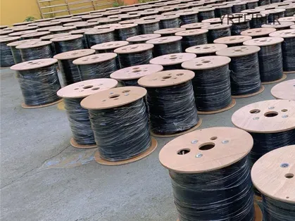
Final Coiling & Packaging Zone
Finished cables are precisely coiled onto wooden or steel reels, wrapped with protective materials, and labeled for shipment.
Ordering & Delivery
Minimum order, lead time and the documents that ship with every order.
Ordering
- Minimum order1 km (1 drum)
- Lead time≤ 300 km: about 15 working days. Over 300 km: confirmed with your order.
- PaymentT/T 30% deposit, balance against B/L copy. L/C at sight accepted.
- InspectionFactory test report plus spot check on arrival. Third-party witness adds 7 working days.
How to order
- 1Send your specification and quantity.
- 2Quotation and datasheet within 24 hours.
- 3Confirm the PI, pay the deposit, production starts.
Delivery & loading
Container loading (reference)
| Fiber count | Drum weight | Drums per 40HQ | km per 40HQ |
|---|---|---|---|
| 144F | 780 kg | 20–23 | 80–92 km |
| 288F | 1,350–1,550 kg | 16–20 | 64–80 km |
Based on 4,000 m drums of outdoor loose-tube cable. Final loading plan is confirmed before shipment.
Fiber and cable diameters vary by model, so the finished drum size — and the number of drums one 40HQ can hold — differ accordingly. The figures above are typical values close to actual loading; for the exact figure please consult our sales manager.
- Port of shipmentQingdao · Guangzhou · Shenzhen
- PackingWooden or steel drum, 2–5 km per drum, length marking every 1 m.
Documents with shipment
- Mill test certificate
- OTDR trace for every drum (bi-directional, 1310/1550 nm)
- Drum no. / length / attenuation table
- Packing list with gross and net weight
- RoHS declaration and CE DoC
- Lifting instructions
Packing & marking for this model
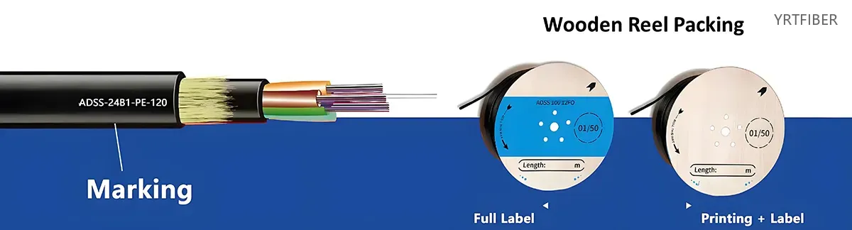
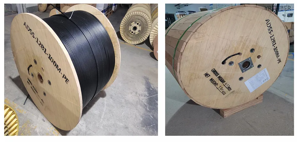
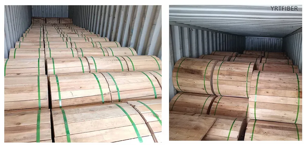
Packaging Requirements:
1:All cables shall be wound on treated wooden spools that are not returnable
2:Cable ends must be firmly secured to the spool and protected with waterproof shrink caps
3:Each spool must include:
Protective plastic wrapping layer
Reinforcing wooden slats for stability
Minimum 1m of free cable end for testing purposes
Standard spool length: 3000m (±2% tolerance allowed)
Cable Identification:
The outer jacket must display:
1、Unique sequential numbering every 1m (±1% variance permitted)
2、 Additional repeating markings at 1m intervals showing:
Product code and fiber count
Manufacturer identification
Production date (month/year)
Total cable length
Standard Packaging Dimensions:
| Length | Container | Size (L×W×H) | Net Mass | Total Mass |
|---|---|---|---|---|
| 2 km | Wood spool | 90×75×90 cm | 156 kg | 220 kg |
| 3 km | Wood spool | 100×68×100 cm | 240 kg | 280 kg |
| 4 km | Wood spool | 109×75×109 cm | 300 kg | 368 kg |
| 5 km | Wood spool | 129×72×129 cm | 400 kg | 480 kg |
Technical Reference:
1、 Cable diameter and weight vary with fiber count and cable construction — see the specification table above.
2、Maximum span depends on cable type and installation design — ask us to confirm for your route.
3、Contact sales team for complete technical specifications
Spool Marking Standards:
Permanent markings (minimum 25-30mm height) must appear on both sides of each spool:
1、 Company name and trademark
2、Contained cable length
3、Cable specifications (type/fiber count)
4、Winding orientation
5、Weight measurements (gross/net)
Note: All wooden packaging materials must undergo proper fumigation treatment prior to use.
Frequently Asked Questions & Quick Inquiry
ADSS-S Fiber Optic Cable FAQ
1. What is an ADSS single jacket fiber optic cable?
ADSS (All-Dielectric Self-Supporting) single jacket cable is a lightweight aerial fiber optic cable that requires no metallic support. It is designed for easy installation along power poles and utility routes without needing a messenger wire.
2. What fiber types and core counts are supported?
The cable supports 2 to 288 fiber cores, using standard single-mode fibers such as G.652D and G.655. This makes it suitable for a range of applications from access to backbone networks.
3. What is the maximum span this cable supports?
It depends on cable OD and the ice/wind zone. Our standard table runs from 160 m (Ø12.5 mm, Zone A) to 1180 m (Ø17.9 mm, Zone A); Zone D caps at 100–900 m. Send your span, ice load, wind speed and sag limit for a matched design.
4. Is the cable resistant to environmental stress?
Yes. The cable’s structure includes a water-blocking gel-filled loose tube, aramid yarn strength members for tensile support, and a outer jacket that offers resistance to UV, moisture, temperature variations, and mechanical stress.
5. What are common applications of this ADSS cable?
ADSS cables are widely used in:
FTTH (Fiber to the Home) rollouts
Power line communication networks
Rural broadband deployment
Backbone fiber optic links in utility corridors
Send Your Inquiry
Fill out the form below and we'll get back to you within 24 hours.
Popular Products

GYXTC8S Self-Supporting Figure 8 Aerial Fiber Optic Cable – G.652D/G.657
GYXTC8S Self-Supporting Figure 8 Aerial Fiber Optic Cable – G.652D/G.657
GYXTC-8Y Self-Supporting Figure 8 Uni-Tube Aerial Fiber Optic Cable
GYXTC-8Y Self-Supporting Figure 8 Uni-Tube Aerial Fiber Optic Cable
ADSS-D Fiber Optic Cable | Double Jacket | 2–288 Cores | G.652D/G.655 | Outdoor Aerial Self-Supporting
ADSS-D Fiber Optic Cable | Double Jacket | 2–288 Cores | G.652D/G.655 | Outdoor Aerial Self-Supporting
GYTC8S Self-Supporting Figure-8 Aerial Fiber Optic Cable – Steel Messenger, Stranded Loose Tube
GYTC8S Self-Supporting Figure-8 Aerial Fiber Optic Cable – Steel Messenger, Stranded Loose Tube
ASU80 Mini ADSS Aerial Self-Supporting Fiber Optic Cable – All-Dielectric, HDPE Sheath
ASU80 Mini ADSS Aerial Self-Supporting Fiber Optic Cable – All-Dielectric, HDPE Sheath
GJYXCH Self-Supporting FTTH Drop Cable – Steel Wire Strength Member, 1/2/4 Core, G652D/G657A
GJYXCH Self-Supporting FTTH Drop Cable – Steel Wire Strength Member, 1/2/4 Core, G652D/G657ARelated Articles
Aerial Fiber Optic Cable: Types, Construction, Applications and Selection Guide
Aerial Fiber Optic Cable: Types, Construction, Applications and Selection Guide
ADSS cable :Application of ADSS optical cable all-dielectric self-supporting in power communication system
ADSS cable :Application of ADSS optical cable all-dielectric self-supporting in power communication system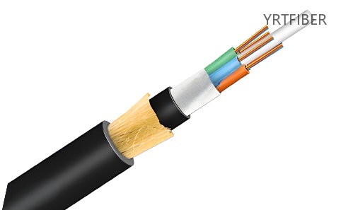
What is the price of ADSS optical cable? A comprehensive analysis of influencing factors and a purchasing guide!
What is the price of ADSS optical cable? A comprehensive analysis of influencing factors and a purchasing guide!
Top Supplier Fiber Optic Cable in China: Leading Manufacturers Premium Solutions
Top Supplier Fiber Optic Cable in China: Leading Manufacturers Premium Solutions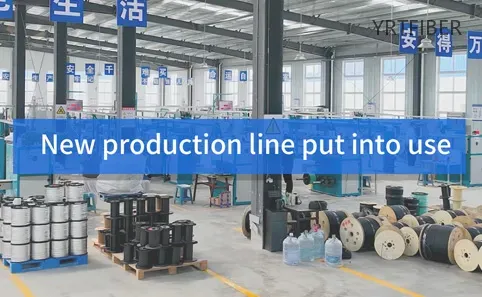
YRT Communication Technology Co., Ltd.'s New Fiber Optic Cable Industrial Park Now Operational
YRT Communication Technology Co., Ltd.'s New Fiber Optic Cable Industrial Park Now Operational