

 Español
 Português
 لالعربية
 Русский
 Bahasa Indonesia
 Français
 Türkçe
 Bahasa Melayu

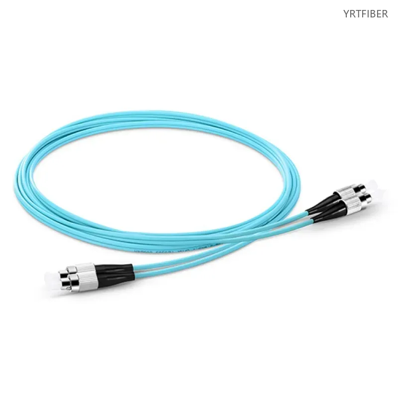
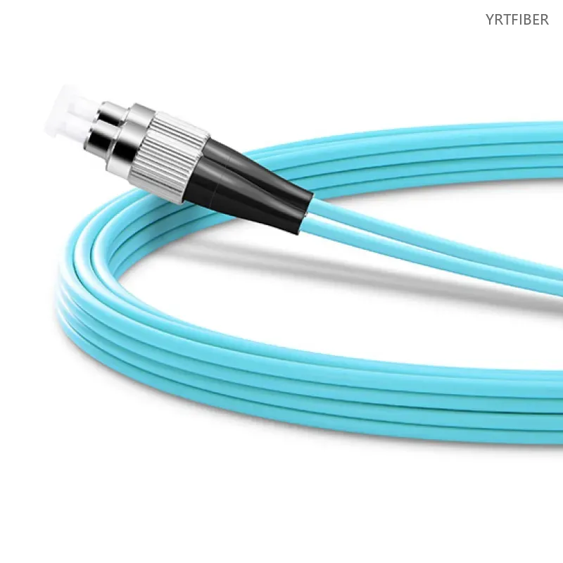
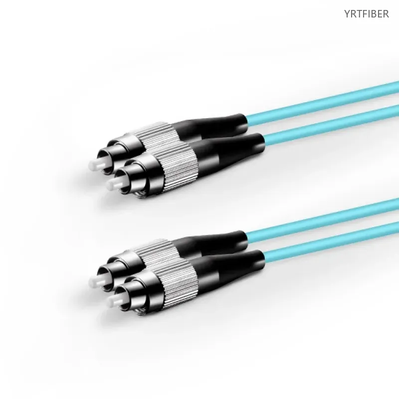
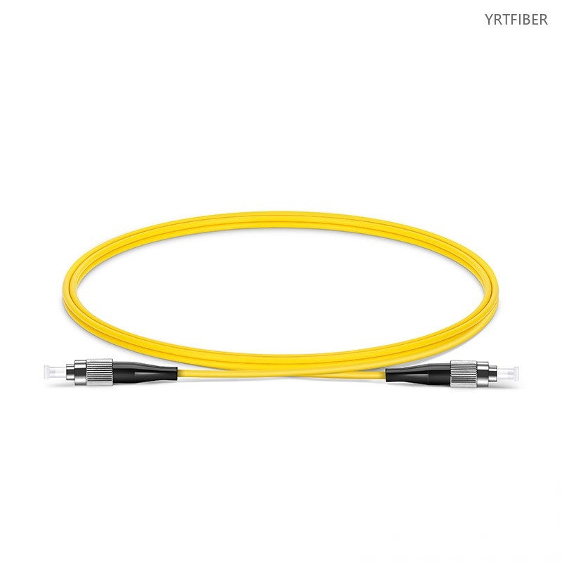
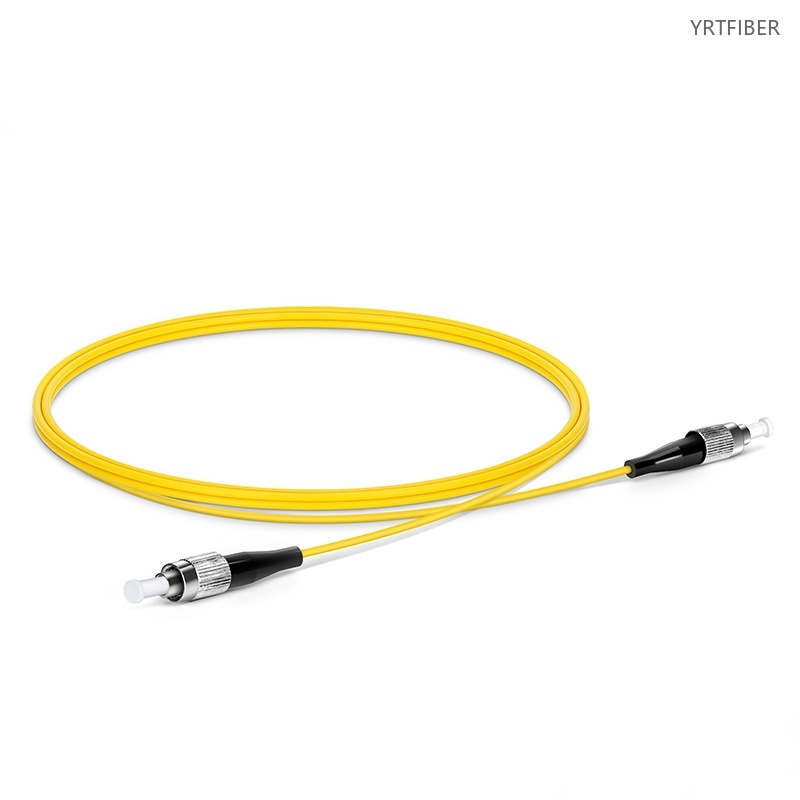
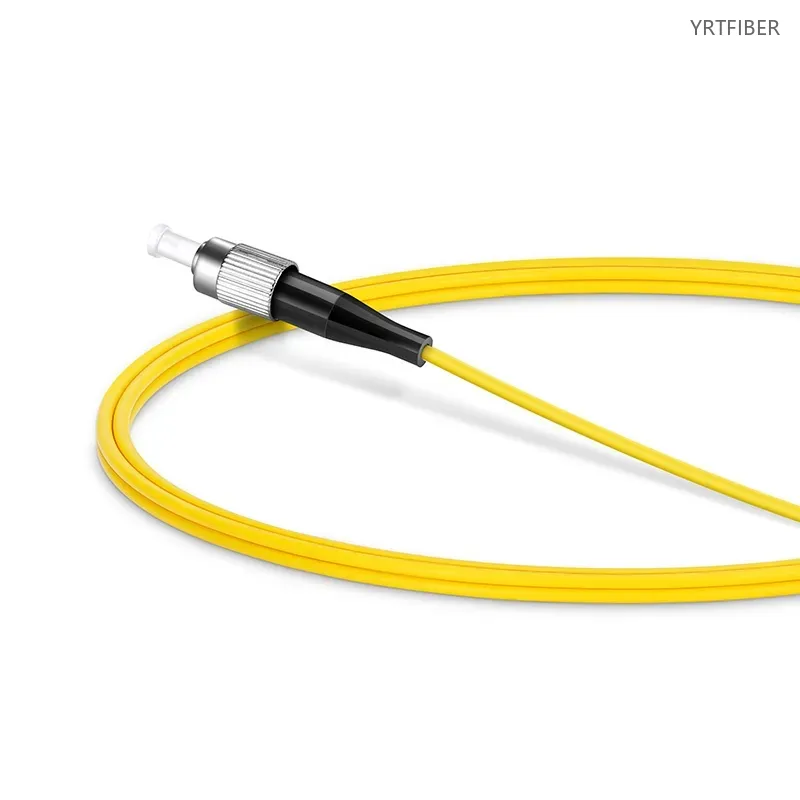
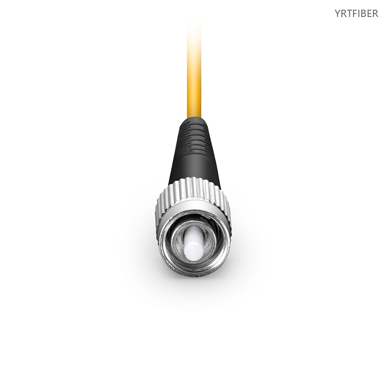
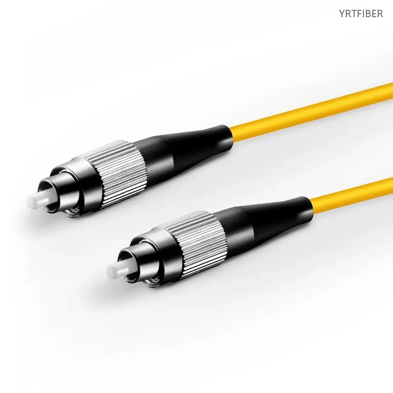
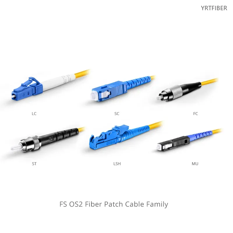
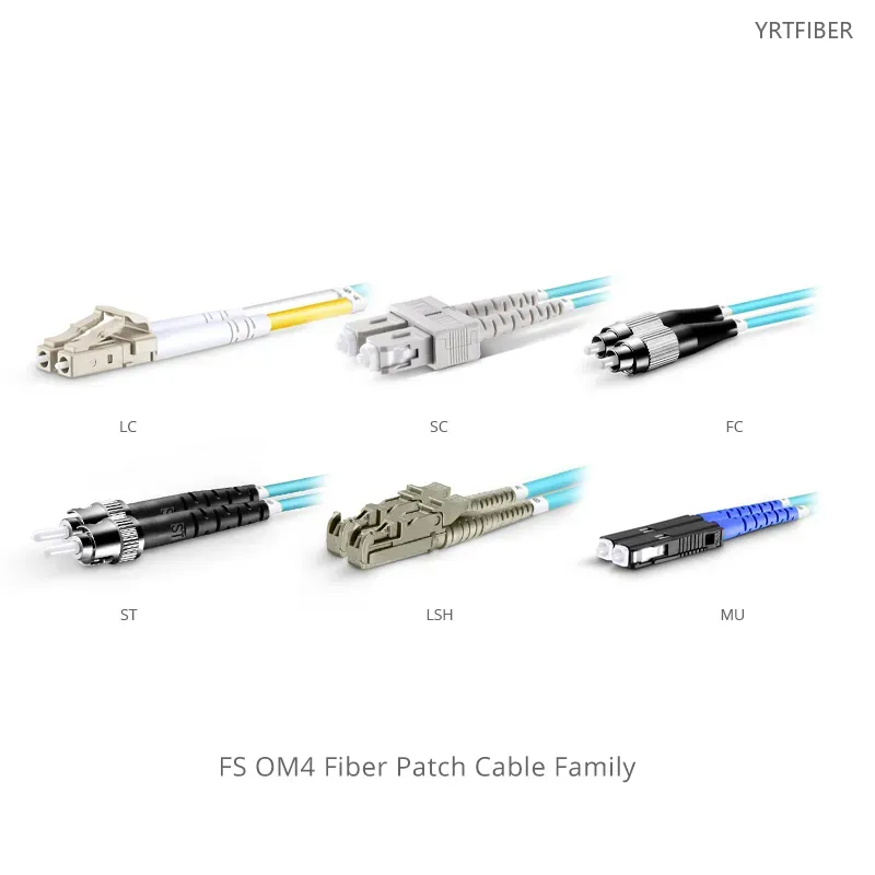
FC-FC UPC Fiber Patch Cable – Simplex OS2 or Duplex OM4, 2.0mm Riser-Rated Jacket
G.657.A1 bend‑insensitive fiber, 10 mm bend radius – fits tight spaces, low loss.
Precision zirconia ferrule connectors – low insertion loss, stable performance.
OFNR riser jacket – safe for vertical in‑building wiring.
Color‑coded jacket – quick identification and management.
Optimized for unidirectional data transmission.
Pre‑terminated, plug‑and‑play – cuts on‑site time and cost.
Reliable for data centers, telecom, and enterprise networks.
What is an FC UPC fiber patch cable?
An FC UPC fiber patch cable is a high‑performance optical jumper terminated with FC connectors featuring Ultra Physical Contact (UPC) polishing for low back reflection. It is designed for reliable interconnect and cross‑connect in entrance facilities, telecom rooms, data centers, and desktop environments. The cable presented here is available in Simplex or Duplex configurations, with Single‑mode OS2 or Multimode OM4 fiber options, and a Riser (OFNR) jacket that meets flame‑retardant requirements for vertical and inter‑floor building installations. Constructed with G.657.A1 bend‑insensitive fiber, it maintains low attenuation even when bent or twisted (minimum bend radius 10 mm), making installation and maintenance more efficient in tight spaces. Precision zirconia ferrule connectors ensure low insertion loss and stable transmission, while the color‑coded jacket simplifies cable management. Optimized for unidirectional data transmission, this pre‑terminated, plug‑and‑play cable reliably supports data centers, telecom networks, and enterprise environments, significantly reducing on‑site installation time and cost.
FC-FC UPC Fiber Patch Cable Specification parameters
- Specification parameters
- OPTICAL CHARACTERISTICS
FC UPC TO FC UPC Simplex
This OS2 fiber patch cable is ideal for connecting 1G/10G/25G/40G/100G/400G Ethernet connections. It is best suited for long distance application and can transport data for up to 10km at 1310nm, or up to 40km at 1550nm.
| Connector A | FC UPC Simplex | Connector B | FC UPC Simplex |
|---|---|---|---|
| Fiber Count | 1 Fiber | Fiber Grade | G.657.A1 (Compatible with G.652.D) |
| Fiber Mode | OS2 9/125μm | Wavelength | 1310/1550nm |
| RoHS Compliancy Status | Compliant | Cable Type | Tight-Buffered |
| Cable Outside Diameter (OD) | 2.0mm | Flame Rating | Riser (OFNR) |
| Min. Bend Radius (Optical Fiber) | 10mm | Min. Bend Radius (Fiber Cable) | 10/5D (Dynamic/Static) |
| Connector Durability | 1000 times | Tensile Strength | 60/100N (Long/Short Term) |
| Insertion Loss | ≤0.3dB | Return Loss | ≥50dB |
| Attenuation at 1310nm | 0.4dB/km | Attenuation at 1550nm | 0.3dB/km |
| Operating Temperature | -10 to 70°C (14 to 158℉) | Storage Temperature | -20 to 70°C (-4 to 158℉) |
FC UPC TO FC UPC Duplex
This OM4 fibre patch cable is ideal for connecting 40G BIDI SR, 10G SR, QSFP+, SFP+ transceivers, etc. for 10/40/100G Ethernet connections and is the preferred fibre specification for 40/100G applications.
| Connector A | FC UPC Duplex | Connector B | FC UPC Duplex |
|---|---|---|---|
| Fiber Count | 2 Fibers | Fiber Grade | G.651 |
| Fiber Mode | OM4 50/125μm | Wavelength | 850/1300nm |
| Polarity | A (Tx) to B (Rx) | Cable Type | Tight-Buffered |
| Cable Outside Diameter (OD) | 2.0mm | Flame Rating | Riser (OFNR) |
| Min. Bend Radius (Optical Fiber) | 15mm | Min. Bend Radius (Fiber Cable) | 20/10D (Dynamic/Static) |
| Connector Durability | 1000 times | Tensile Strength | 90/150N (Long/Short Term) |
| Insertion Loss | ≤0.3dB | Return Loss | ≥30dB |
| Attenuation at 850nm | 3.5dB/km | Attenuation at 1300nm | 1.5dB/km |
| Operating Temperature | -10 to 70°C (14 to 158℉) | Storage Temperature | -20 to 70°C (-4 to 158℉) |
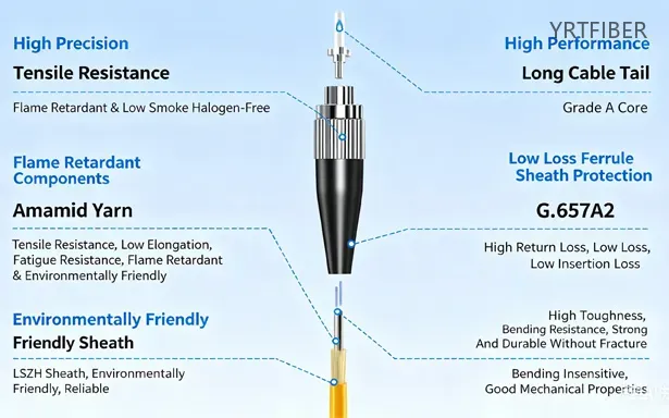
Product Structure & Composition
Fiber core & cladding: 9/125 µm (OS2 single mode) or 50/125 µm (OM4 multimode) glass for light transmission.
Coating & strength members: Acrylate coating over cladding, surrounded by aramid yarn for tensile strength.
Outer jacket: PVC, LSZH, or OFNP; color-coded yellow (OS2) or aqua/violet (OM4).
FC connector: Threaded nickel‑plated brass body, 2.5 mm zirconia ceramic ferrule, spring‑loaded.
UPC polish: Domed endface providing return loss ≥50 dB, minimizing back reflection.
Strain relief: Flexible rubber boot at the cable‑to‑connector junction.
simplex / duplex
Benefits of FC-FC UPC Fiber Patch Cable
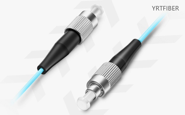
Secure FC Connector with Precision Ceramic Ferrule
The FC connector features a threaded nickel-plated brass body for vibration-resistant locking, combined with a 2.5 mm zirconia ceramic ferrule that ensures low insertion loss (≤0.3 dB typical) and high alignment durability over repeated mating cycles.
UPC Polishing for Low Back Reflection
Ultra Physical Contact (UPC) polish with a slightly domed endface achieves a return loss of ≥50 dB, minimizing signal reflections and ensuring stable transmission in sensitive single-mode and multimode applications.
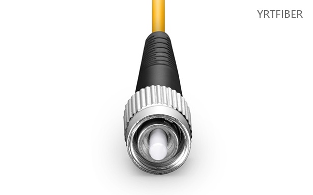
Durable Construction with Color-Coded Jacket Options
Aramid yarn strength members provide high tensile resistance, while outer jackets (PVC, LSZH, or OFNP) meet indoor/plenum fire safety ratings. Yellow (OS2) or aqua/violet (OM4) jackets enable quick visual identification, and the cable supports a wide operating temperature range from -20°C to +70°C.
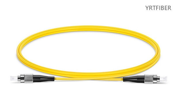
Simplex or Duplex Configuration for Flexible Deployment
Available in simplex (single fiber) for point-to-point links or duplex (two fibers with clip/zipper design) for parallel transceiver applications such as 40G/100G Ethernet, Fibre Channel, or bidirectional communication systems.

Engineering Applications FC-FC UPC Fiber Patch Cable
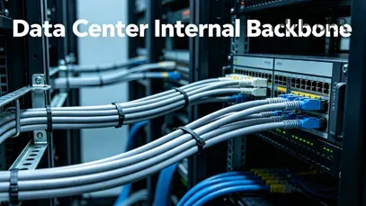
OS2 Fiber Patch Cable - Long-Haul Telecom & High-Precision Test
This cable is widely deployed in telecommunications backbone networks, metropolitan area networks (MANs), and CATV headends where single-mode transmission over several kilometers is required. Its FC/UPC connectors provide stable, low-back-reflection connections for optical time-domain reflectometers (OTDRs), optical spectrum analyzers (OSAs), and other lab test equipment. It is also used in fiber-to-the-antenna (FTTA) for 5G fronthaul and in long-distance sensing systems (e.g., DTS/DAS) that demand minimal signal attenuation at 1310 nm or 1550 nm.

OM4 Fiber Patch Cable - Data Center & Enterprise Backbone
This duplex multimode cable is ideal for short-reach, high-bandwidth applications such as 40G/100G Ethernet links within data centers (e.g., between top-of-rack switches and aggregation switches), storage area networks (SANs) using Fibre Channel (16G/32G), and high-performance computing (HPC) clusters. OM4 fiber supports up to 400 meters at 100 Gb/s (SR4) and is commonly used in corporate building backbones, campus LANs, and AV over IP installations where low-cost VCSEL transceivers are preferred. The FC connector ensures secure, vibration-resistant connections in industrial or lab environments.
Shipping & Packaging
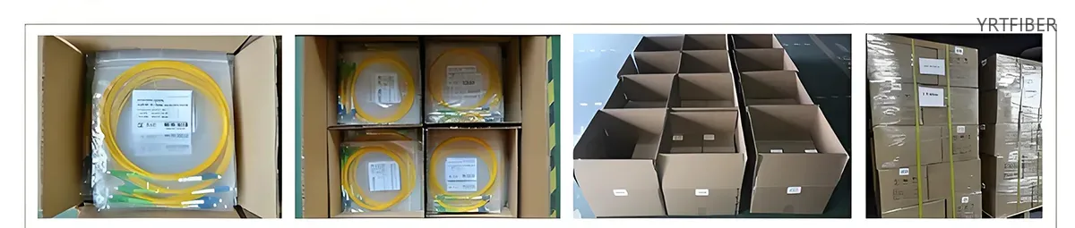

Product Comparison:
FC/UPC vs LC/UPC
| Feature / Dimension | FC/UPC Fiber Patch Cable | LC/UPC Fiber Patch Cable |
|---|---|---|
| Structure / Form Factor | Metal body, threaded barrel housing with nickel-plated finish. Utilizes a round screw-type coupling mechanism. 2.5 mm ceramic ferrule. Simplex or duplex configurations available. | Small form-factor (SFF) plastic body with push-pull latching mechanism. 1.25 mm ceramic ferrule (half the size of FC/SC). Often used in duplex format with a clip holding two connectors together. |
| Typical Applications | Test equipment, measurement labs, industrial networks, harsh/vibration‑prone environments, legacy telecom systems, single-mode networks. | Data centers, high‑density patch panels, enterprise LANs, SFP/SFP+ transceivers, FTTH (modern ODN), switches and servers. |
| Key Engineering Pros | ① Excellent vibration resistance – threaded screw coupling provides the highest mechanical stability among common connectors. ② Robust metal housing – withstands harsh industrial environments and repeated use. ③ Low insertion loss (≤0.35 dB typical). ④ Reliable and durable, suitable for field termination. | ① High port density – 1.25 mm ferrule allows twice the port count per rack unit compared to FC/SC. ② Fast and intuitive – push‑pull latch enables quick patching and changes. ③ Low insertion loss (≤0.35 dB typical). ④ Dominant standard for modern transceivers (SFP, SFP+, QSFP). ⑤ Duplex clip ensures correct Tx/Rx polarity. |
| Key Engineering Cons | ① Slower to connect/disconnect – requires rotating the nut, unsuitable for frequent patching. ② Large form factor – occupies significant panel space, limiting port density. ③ More prone to cross‑threading when rushed. ④ Declining in modern networks – being phased out in favor of smaller connectors. | ① Plastic body – less robust than FC’s metal housing for harsh environments. ② Lower vibration resistance compared to FC’s screw coupling. ③ Can be fiddly to disengage in tight spaces if latch is inaccessible. ④ Higher material cost than FC in some markets due to tighter manufacturing tolerances. |
| Tolerance to Vibration / Shock | Excellent – threaded coupling maintains stable connection under vibration, ideal for industrial and mobile applications. | Good, but latch may loosen under sustained vibration. Better suited for stationary indoor environments. |
| Connection Speed | Slow – requires multiple rotations to secure. Not ideal for frequent changes or dynamic patching. | Fast – simple push‑pull action enables rapid deployment and reconfiguration. |
| Cable Jacket Options | PVC (OFNR), LSZH, Plenum (OFNP). Available in simplex or duplex round cable. | PVC (OFNR), LSZH, Plenum (OFNP). Available in simplex, duplex (2.0 mm or 3.0 mm round), or uniboot designs. |
| Fiber Mode Options | Singlemode OS2 (9/125 μm) – common; multimode OM3/OM4/OM5 also available. | Singlemode OS2 and multimode OM3/OM4/OM5. Bend‑insensitive fibers (G.657.A1/A2) widely available. |
| Cost (Relative) | Medium – metal housing and precision machining add cost, but mature manufacturing keeps pricing competitive. | Medium – higher per-unit cost than FC in some markets due to denser manufacturing tolerances, but comparable overall. |
| Maintenance & Handling | Cleaning requires access to the threaded barrel; removal takes longer. Cross‑threading risk when re‑attaching. | Easy to clean – latch mechanism allows quick removal. No cross‑threading risk. Dust cap fits securely. |
FC-FC UPC Fiber Patch Cable Selection Guide
FC/UPC and LC/UPC fiber patch cables serve fundamentally different deployment scenarios. The choice is primarily driven by mechanical robustness vs. port density and operational convenience.
For fiber optic test equipment, measurement laboratories, and industrial environments with significant vibration or shock, FC/UPC is the preferred choice.
The threaded screw coupling provides the highest mechanical stability among common fiber connectors, maintaining consistent insertion loss even under vibration or movement. The robust metal housing withstands harsh industrial conditions, making FC/UPC ideal for factory floors, R&D labs, outdoor test setups, and legacy telecom central offices where FC‑based termination panels remain installed. However, FC/UPC is not recommended for high‑density patching or environments requiring frequent changes – the screw‑on design is slower to connect and more prone to cross‑threading when rushed.
For modern data centers, enterprise networks, and high‑density equipment rooms, LC/UPC is the dominant standard.
The 1.25 mm ferrule doubles the port density compared to FC/SC connectors, allowing more ports per rack unit. The push‑pull latch enables fast patching and reconfiguration, essential for dynamic data center operations. LC/UPC is also the standard interface for SFP, SFP+, and QSFP transceivers used in switches, servers, and active equipment. For greenfield FTTH deployments and modern telecom central offices, LC is rapidly replacing FC as the default connector type.
| Parameter | Best Fit |
|---|---|
| High vibration / industrial environments | FC/UPC |
| High‑density data center patching | LC/UPC |
| Frequent changes / dynamic patching | LC/UPC |
| Legacy test & measurement systems | FC/UPC |
| SFP/QSFP transceiver connectivity | LC/UPC |
| Outdoor / harsh conditions | FC/UPC (with reinforced housing) |
| Cost‑sensitive static patching | FC/UPC (comparable cost, lower density) |
Mixed deployment guidance: Where existing FC‑based equipment must interface with modern LC‑based transceivers, use hybrid patch cords (FC/UPC to LC/UPC). For high‑density data center environments requiring thousands of terminations, LC/UPC is the practical standard. For laboratory and industrial test setups where ruggedness outweighs density, FC/UPC remains a solid choice.
Installation instructions for FC-FC UPC fiber patch cable
Preparation & Inspection
Inspect both FC connectors for dust or damage using a fiber scope. Clean the ceramic ferrule endfaces with lint-free wipes and isopropyl alcohol if needed. Do not touch the polished surface.
Alignment & Mating
Align the connector's key slot with the adapter’s alignment key. Gently push the connector into the FC adapter until seated, then tighten the threaded coupling nut hand‑tight (do not over‑torque).
Securing & Strain Relief
Ensure the nut is snug to prevent vibration loosening. Route the cable with a minimum bend radius of 10× the cable diameter and secure it with clips or Velcro to avoid tension on the connector.
Testing & Verification
After installation, verify link performance using a light source and power meter or an OTDR to measure insertion loss and return loss against required specifications.
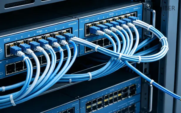
Download YRTFIBER Product Catalog
Factory Real Shot
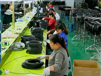
State-of-the-Art Manufacturing Facilities
Our 12,000 sqm dust-proof workshop houses over 30 automated production lines for single-core and MPO patch cords. Equipment includes high-precision fiber cutters (±0.08 mm tolerance), FLC automatic termination machines, and UV curing systems, enabling a daily output of thousands of connectors with consistent quality.
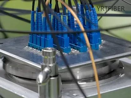
Precision Core Manufacturing Process
The process starts with micro-tolerance cutting (end-face angle ±0.5°) and six-axis fusion splicing (core deviation ≤1 μm). After multilayer jacketing with LSZH, PVC, or OFNP, connectors are polished on automated lines for PC, UPC, or APC finishes, achieving up to 7,000 connectors per 11-hour shift.
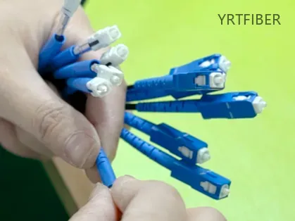
Rigorous Quality Assurance & Testing
Every patch cord undergoes 100% inspection: interferometric end-face analysis (400x), automatic contamination detection, and insertion/return loss testing via OTDR. Environmental samples also pass temperature, humidity, and pull-force tests per IEC/TIA standards.
Frequently Asked Questions & Quick Inquiry
FC-FC UPC Fiber Patch Cable FAQ
Can I connect a UPC connector to an APC connector?
No, UPC and APC connectors should never be mixed or directly connected. UPC connectors have a flat (0°) endface, while APC (Angled Physical Contact) connectors feature an 8° angled endface. Attempting to connect them creates a physical mismatch — the angled and flat surfaces cannot fully align, leaving an air gap that causes signal attenuation of up to 20 dB or more. This mismatch can permanently damage both connectors and should be avoided. To ensure proper mating, the polish type (UPC or APC) must be the same on both connectors and on the adapter in between.
Where are FC/UPC fiber connectors typically used?
FC/UPC connectors are most commonly used in singlemode fiber applications that require a secure, vibration-resistant connection. Typical applications include telecommunications backbone networks, CATV distribution, optical test and measurement equipment (such as OTDRs and optical spectrum analyzers), fiber optic sensors, and laboratory instruments. Due to their threaded locking mechanism, FC connectors are particularly favored in high-vibration environments like industrial settings, outdoor telecom cabinets, and aerospace or military systems. They are also used in FTTH systems and passive optical networks where stable, low-loss connections are required.
How do FC connectors compare to SC and LC connectors?
FC, SC, and LC are the three most common fiber optic connector types, each with distinct characteristics. The FC connector features a threaded screw-on metal housing that provides the most secure mechanical connection, making it ideal for high-vibration environments. However, FC connectors require more careful mating due to the need to align the key and risk of scratching the fiber endface, and their use is becoming less common in favor of SC and LC. In contrast, SC connectors use a push-pull latching mechanism (often called "square connector") and are widely used in FTTH and data networks, while LC connectors feature a smaller 1.25 mm ferrule (half the size of FC/SC) and are the dominant choice for high-density applications like data center patch panels.
What is the difference between single mode and multimode FC adapters?
The main difference lies in alignment precision and intended transmission distance. Single mode FC adapters are optimized for long-distance, low-loss transmission with precise core alignment (typically using a zirconia ceramic sleeve), while multimode adapters are designed for shorter distances with higher bandwidth requirements (often using a phosphorus bronze sleeve, though zirconia is increasingly used for both). Single mode adapters offer more precise alignment and can also be used to connect multimode cables, but multimode adapters should not be used with single mode cables as the lower precision can cause alignment problems and significant signal loss. Additionally, single mode FC adapters typically have a blue or yellow identifier, while multimode versions are often beige or black.
Can you convert LC to SC?
Yes, you can convert an LC connector to an SC connector using a **hybrid fiber optic adapter** (also called a coupler or converter). These adapters have different connector ports on each side—one that accepts an LC connector and the other that accepts an SC connector. Hybrid LC to SC adapters are widely available in simplex or duplex configurations, for both single mode (SM) and multimode (MM) applications, and with either UPC or APC polish types. They are commonly used in data centers, patch panels, and FTTH installations to interconnect equipment with different connector types without replacing existing cables.
What is the difference between SC and FC?
SC (Subscriber Connector) and FC (Ferrule Connector) differ mainly in their coupling mechanism, body material, and typical applications. **FC** connectors feature a metal housing with a threaded screw-on coupling, making them highly secure and vibration resistant; they are commonly used on patch panels (ODF side) and in high-vibration environments, such as telecom cabinets and test equipment. **SC** connectors use a square plastic housing with a push-pull latching mechanism, offering easier one-handed operation; they are the most widely used connector on router switches and transmission equipment due to their durability and ease of use. Additionally, LC is a smaller, high-density variant of the SC design, with LC taking up about half the space of an SC connector.
Can you mix APC and UPC fiber?
No, you should never directly connect an APC connector to a UPC connector. APC (Angled Physical Contact) ferrules have an 8‑degree angled endface, while UPC (Ultra Physical Contact) ferrules have a slightly domed but flat endface. Directly mating an APC connector with a UPC connector creates a physical gap and misalignment, resulting in extremely high insertion loss and permanently damaging both connectors. However, you can interconnect APC and UPC fibers using a **hybrid adapter** specifically designed for this purpose (e.g., SC/APC to FC/UPC). Such adapters are available from suppliers like FS.com and ensure proper alignment while accommodating the different endface geometries.
Send Your Inquiry
Fill out the form below and we'll get back to you within 24 hours.
Related Articles

LC-LC UPC Simplex/Duplex Single Mode (OS2) Fiber Patch Cable – Riser (OFNR), 2.0mm Tight-Buffered
LC-LC UPC Simplex/Duplex Single Mode (OS2) Fiber Patch Cable – Riser (OFNR), 2.0mm Tight-Buffered
SC-SC UPC OS2 Fiber Patch Cord | Simplex & Duplex Riser (OFNR) Jumper
SC-SC UPC OS2 Fiber Patch Cord | Simplex & Duplex Riser (OFNR) Jumper


