

 Español
 Português
 لالعربية
 Русский
 Bahasa Indonesia
 Français
 Türkçe
 Bahasa Melayu
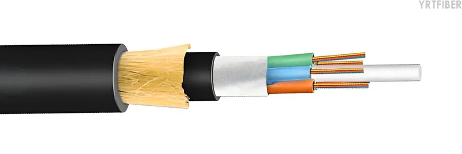
All-dielectric self-supporting (ADSS) and Figure-8 are the two main types of self-supporting aerial fiber optic cables. ADSS uses non-metallic aramid yarn strength members to carry its own weight without a separate messenger, making it suitable for installation near high-voltage power lines. Figure-8 cable integrates an optical fiber core with a steel messenger wire through a common polyethylene sheath, forming a cross-section that resembles the number “8,” and is designed for economical aerial deployment on standard telecom pole routes. This article compares the two cable types across structure, mechanical performance, electrical safety, installation, cost, and application scenarios to support engineering selection.
What Are ADSS and Figure-8 Aerial Fiber Cables?
ADSS (All-Dielectric Self-Supporting) is an aerial cable that carries its own weight and tension between structures without a separate messenger wire. Instead of steel, the tensile load is carried by non-metallic strength members-typically aramid yarn with FRP or glass-reinforced elements. The cable contains no metallic components and is fully dielectric. ADSS is standardized under IEC 60794-4-20 for aerial optical cables along electrical power lines and under IEEE 1222 for utility power line applications.
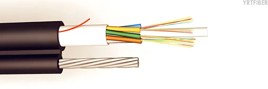
Figure-8 Cable (also known as integral messenger cable) is a self-supporting aerial cable consisting of an optical fiber cable core and an integrated stranded steel messenger. Both the cable and the messenger share a common outer PE jacket, resulting in a figure-8 cross-section. The steel messenger bears the installation and long-term tensile loads, allowing the cable to be suspended between poles without placing undue stress on the optical fibers. Common model designations include GYTC8S (layer-stranded) and GYXTC8S (central tube type).
An important distinction: optical fiber manufacturing produces the glass fiber itself, while fiber optic cable manufacturing converts finished optical fibers into protected cable structures. Both ADSS and Figure-8 are cable types-they use the same optical fibers but package them differently for aerial deployment.
Structural Comparison
| Feature | ADSS Cable | Figure-8 Cable |
|---|---|---|
| Cross-section | Round, single-body | Figure-8, two-part integrated |
| Strength member | Non-metallic (aramid yarn, FRP) | Steel messenger wire |
| Metallic content | None; fully dielectric | Conductive steel messenger |
| Fiber count range | Typically 12-288 fibers | Typically 2-144 fibers |
| Outer sheath | PE or AT (anti-tracking) for high-voltage | UV-resistant PE |
| Water blocking | Water-blocking gel and swelling tape | Full-section water-blocking technology |
ADSS Cable Construction
ADSS consists of single-mode optical fibers contained in one or more protective dielectric fiber optic units, surrounded by or attached to suitable dielectric strength members and sheaths. The typical construction includes: optical fibers in gel-filled loose tubes stranded around a central strength member, water-swelling tape wrapped around the core, aramid yarns helically laid for peripheral strengthening, and an outer PE or AT jacket. When surface induction exceeds 12kV, an anti-tracking (AT) sheath is applied; with AT outer jacket, the maximum electric field strength at the operating point can reach 35kV.
Figure-8 Cable Construction
Figure-8 cable has two integrated components:
Upper section (messenger): High-strength galvanized steel strand providing tensile strength for self-supporting overhead installation.
Lower section (optical cable core): Optical fibers (typically 250μm) in gel-filled loose tubes, stranded around a central strength member (steel or FRP), with PSP (plastic-coated steel strip) or water-blocking tape, and a UV-resistant PE outer sheath.
Connecting bridge: The messenger and cable core are joined by the same PE Sheath, forming a stable figure-8 structure.
Mechanical Performance Comparison
| Parameter | ADSS Cable | Figure-8 Cable |
|---|---|---|
| Typical maximum span | Up to 800-1500 meters | Typically 50-150 meters |
| Short-term tensile strength | Model-dependent; RTS ≥;9 kN typical | Up to 8000N (GYTC8S example) |
| Long-term tensile strength | Model-dependent | Up to 2700N (GYTC8S example) |
| Crush resistance | ≥;2 kN/100mm | 2000N/100mm short-term |
| Minimum bend radius (installation) | Varies by design | 20×OD |
| Operating temperature | Varies by design | -40°C to +70°C |
Important: Values must not be generalized across all cable models. Actual mechanical specifications depend on fiber count, span design, and environmental conditions. Always refer to the specific product data sheet for the intended cable
ADSS achieves long spans through the exceptional strength-to-weight ratio of aramid yarn, which can span distances exceeding 800 meters depending on design and environmental conditions. Figure-8 cable is typically designed for short to medium spans (50-150 meters).
Electrical Safety and Environmental Suitability
ADSS Cable
Fully dielectric: No metallic components, immune to electromagnetic interference (EMI) and electrostatic discharge.
Suitable for high-voltage environments: Can be installed in the strong electric fields near energized conductors, typically in the neutral space of power transmission towers.
No grounding required: Eliminates grounding complexity and cost.
AT sheath option: For surface induction above 12kV.
Figure-8 Cable
Conductive messenger: Steel messenger requires grounding and bonding when installed near power infrastructure.
NESC clearance requirements: Must maintain specified clearances from energized conductors.
Corrosion risk: Steel messenger requires periodic corrosion inspection, especially in coastal or industrial environments.
Not suitable for high-voltage power corridors: Generally limited to routes under 66kV.
Installation Comparison
| Aspect | ADSS Cable | Figure-8 Cable |
|---|---|---|
| Installation method | Single-pass; self-supporting | Single-pass; integrated messenger |
| Hardware required | Suspension clamps, dead-end assemblies | Messenger clamps, lashing hardware |
| Installation complexity | Higher; requires sag-tension engineering | Lower; standard pole attachment |
| Installation speed | Moderate | Faster; 30-50% labor savings vs. traditional lashing |
| Special considerations | Sag design, anti-tracking sheath selection | Messenger tensioning, grounding |
Figure-8 cable offers faster installation because the steel messenger is pre-integrated with the cable, eliminating the separate step of installing a messenger wire and then lashing the cable. ADSS installation requires more engineering attention to sag-tension design and hardware matching.
Cost and Total Cost of Ownership (TCO)
| Cost Factor | ADSS Cable | Figure-8 Cable |
|---|---|---|
| Cable material cost | Higher (aramid yarn, specialized sheath) | Lower (steel messenger, standard PE) |
| Fittings and hardware | Higher | Lower |
| Installation labor | Moderate to higher | Lower |
| Maintenance cost | Lower (no corrosion, no grounding) | Higher (steel messenger corrosion inspection) |
| 20-25 year TCO | Up to 40% lower than Figure-8 | Higher due to maintenance |
While Figure-8 cable has lower upfront material and installation costs on standard routes, ADSS can offer lower total cost of ownership over a 20-25 year lifecycle due to reduced maintenance requirements.
Suitable and Unsuitable Applications
ADSS Cable - Suitable For
Power transmission and distribution corridors
Medium- and high-voltage lines sharing structures with energized conductors
Routes where metallic components are not allowed
Long-span aerial crossings (rivers, valleys, mountains)
Environments requiring electrical isolation
ADSS Cable - Not Suitable For
Short, low-cost distribution routes where Figure-8 would suffice
Routes where local installation crews lack ADSS hardware and training
Applications where aramid yarn strength members are cost-prohibitive
Figure-8 Cable - Suitable For
Telecom access networks on standard utility poles
Rural broadband and last-mile FTTH distribution
Budget- and schedule-driven builds
Routes with no high-voltage power infrastructure nearby
Campus and enterprise aerial deployments
Figure-8 Cable - Not Suitable For
High-voltage power line corridors (above 66kV)
Long spans exceeding 150-200 meters
Environments where steel messenger corrosion is a concern
Routes requiring all-dielectric construction for electrical safety
Selection Checklist
When choosing between ADSS and Figure-8 cable for an aerial project, evaluate the following factors:
Voltage environment: Is the route near energized power lines? If yes, consider ADSS for electrical safety.
Span length: Are spans under 150 meters? Figure-8 may be sufficient. Over 200 meters? ADSS is typically required.
Metallic allowance: Are metallic components permitted? If not, ADSS is mandatory.
Grounding capability: Can the messenger be grounded? If grounding is complex or costly, ADSS avoids this issue.
Budget horizon: Is the project budget-driven or TCO-driven? Figure-8 for lower upfront cost; ADSS for lower long-term cost.
Environmental conditions: Is there risk of corrosion (coastal, industrial)? ADSS eliminates this concern.
Installation crew expertise: Are installers familiar with ADSS hardware and sag-tension design?
Future voltage upgrades: Will line voltage increase in the future? ADSS is the safer choice.
Frequently Asked Questions
Is ADSS always better than Figure-8 cable?
No. Neither cable is universally better. ADSS is the right choice for power corridors and long spans; Figure-8 is the right choice for standard telecom pole routes with short spans and budget constraints.
Can Figure-8 cable be installed near power lines?
Yes, but with limitations. Figure-8 cable should be kept away from high-voltage lines (generally under 66kV) and must maintain NESC clearance requirements with the steel messenger properly grounded.
What is the maximum span for ADSS cable?
ADSS span capacity depends on design, fiber count, environmental conditions (wind, ice), and sag requirements. Typical maximum spans range from 800 to over 1500 meters. Always consult the specific product data sheet.
What is the typical span for Figure-8 cable?
Figure-8 cable is generally designed for spans of 50 to 150 meters. Some designs may reach 200 meters under favorable conditions.
Does ADSS require grounding?
No. ADSS contains no metallic components and does not require grounding. This is one of its key advantages in power line environments.
Does Figure-8 cable require maintenance?
Yes. The steel messenger requires periodic inspection for corrosion, especially in coastal or industrial environments. Grounding connections should also be periodically verified.
Which cable has lower total cost of ownership?
ADSS typically has lower TCO over a 20-25 year lifecycle, with some estimates showing up to 40% lower cost than Figure-8 when maintenance is factored in. However, Figure-8 has lower upfront costs.
Conclusion
ADSS and Figure-8 are both self-supporting aerial fiber optic cables, but they serve different engineering needs. ADSS is the all-dielectric solution for high-voltage power corridors, long spans, and environments where electrical isolation is critical-at a higher initial cost but lower long-term maintenance. Figure-8 cable is the economical workhorse for standard telecom pole routes, short to medium spans, and budget-conscious deployments-with lower upfront cost but higher maintenance requirements.
The correct choice depends on span length, voltage environment, metallic allowance, grounding capability, budget horizon, and maintenance resources. Neither type is inherently superior; each is optimized for specific aerial deployment scenarios.
References
IEC 60794-4-20:2018 - Sectional specification for ADSS (all dielectric self-supported) optical cables along electrical power lines,
IEC 60794-1-119:2025 - Test procedures for aerial optical fibre cables including ADSS
National Electrical Safety Code (NESC) - Clearance requirements for aerial cables


